
DIY tiny Arduboy based on Arduino pro micro
It took me some months (!!) so I could invest a few hours to build my own arduboy. I had bought all needed parts a long time ago, but so many projects to do… 😉
Nonetheless, it’s done and it was pretty simple, but yet fun to do. You will find below all the build steps…
Objective
As a fan of both retrogaming and DIY electronic gadgets, I liked the Arduboy platform and decided to build a clone. I did not used a lipo battery to power it, but alkaline ones, just for the fun, even if it makes the console bigger at the end (but massive battery life of 30+ hours, and more “retro”)
Needed parts
I used an Arduino pro micro as motherboard, which is not exactly “supported” by the Arduboy framework out of the box. Nevertheless, “MrBlinky” has made a custom framework which is fully compatible with Arduboy ecosystem and support alternative hardware, providing you wire everything correctly : https://github.com/MrBlinky/Arduboy-homemade-package/blob/master/README.md
Here are all the parts I used: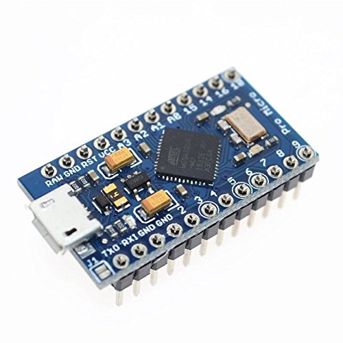
- An Arduino Pro Micro 5v 16 Mhz
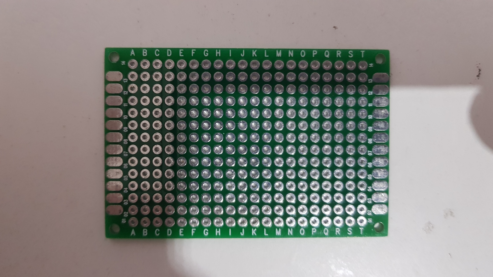
- One 4×6 centimeters Prototype Pcb
- One “5 Directions” tactile Switch, SMD 6 Pins 10x10x9mm
- Various U shape solderless breadboard jumper cable
- One mini slide switch
- One piezo ceramic wafer
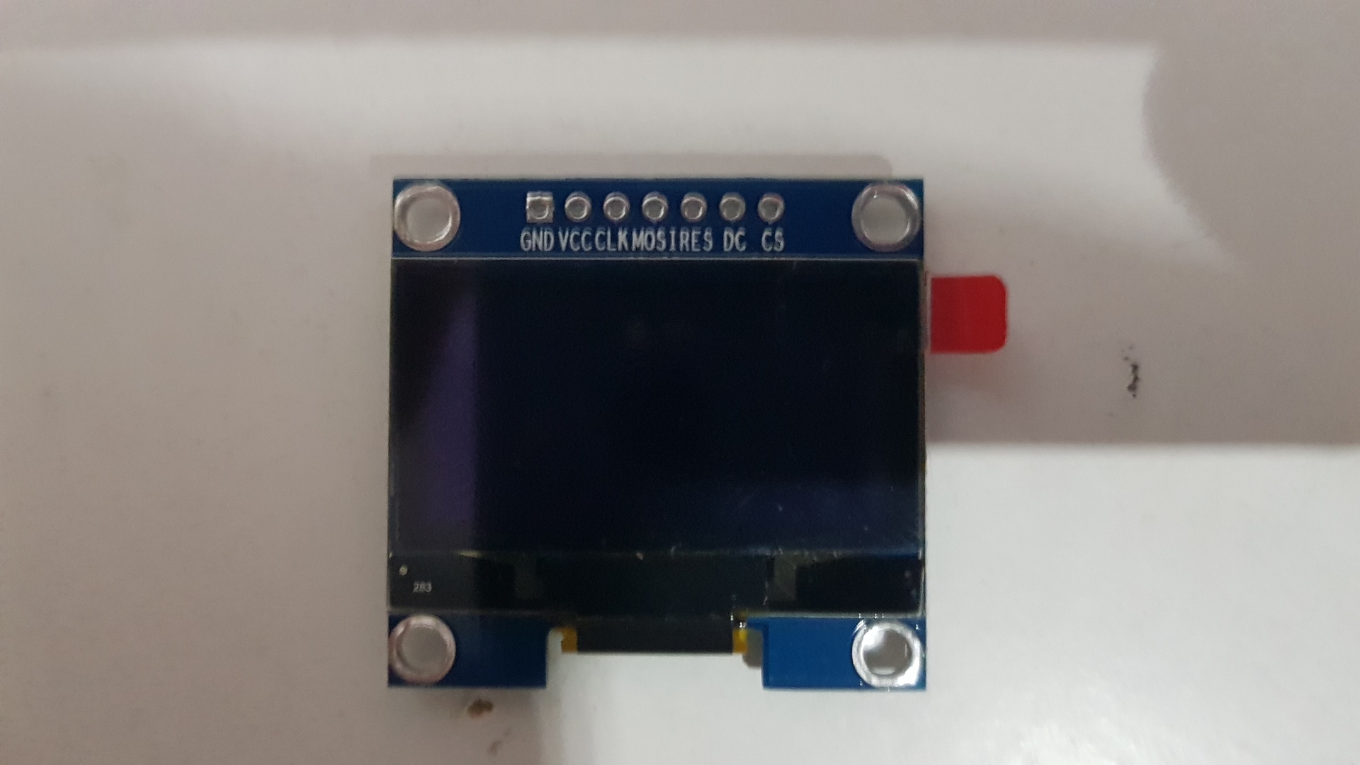
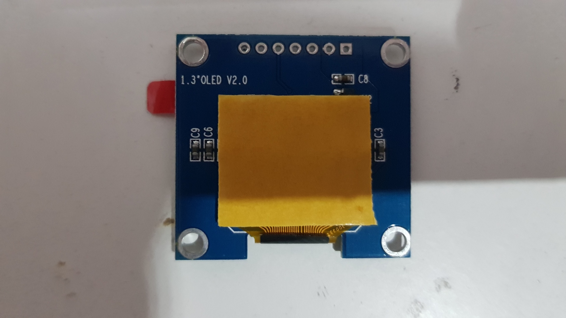
- An 1.3″ I2C IIC SPI Serial 128X64 White OLED LCD (7Pin, SH1106 controller)
- A 2-5v to 5v step-up converter
- Two micro tactile switch 6×6 mm
- Three leds, 3 mm (red, green and blue, as I did not have an rgb one…)
- Three resistors
- A ribbon cable (an old IDE or floppy one)
- AAA battery springs and noses
- Some thermal pad
- Double sided adhesive
Build Steps
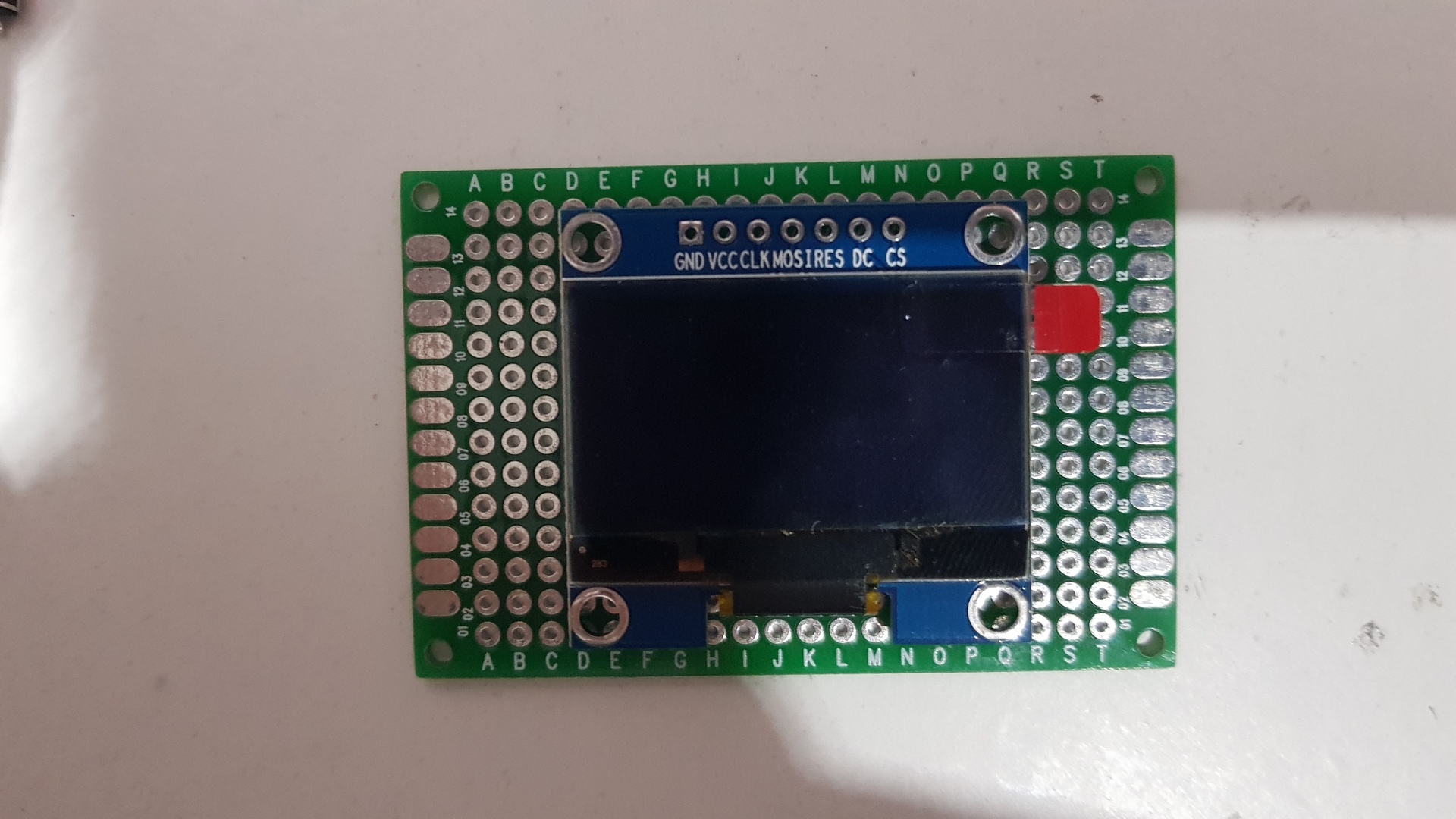
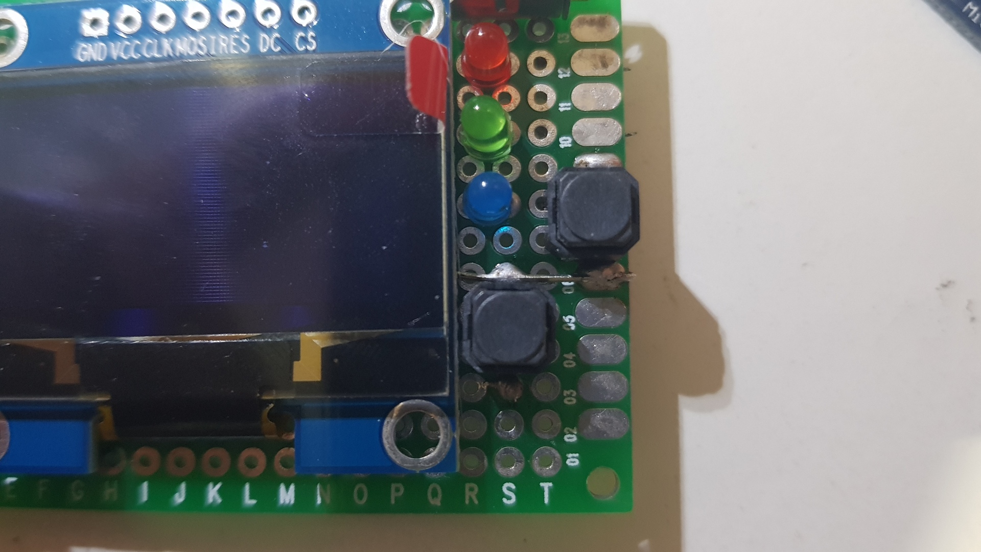
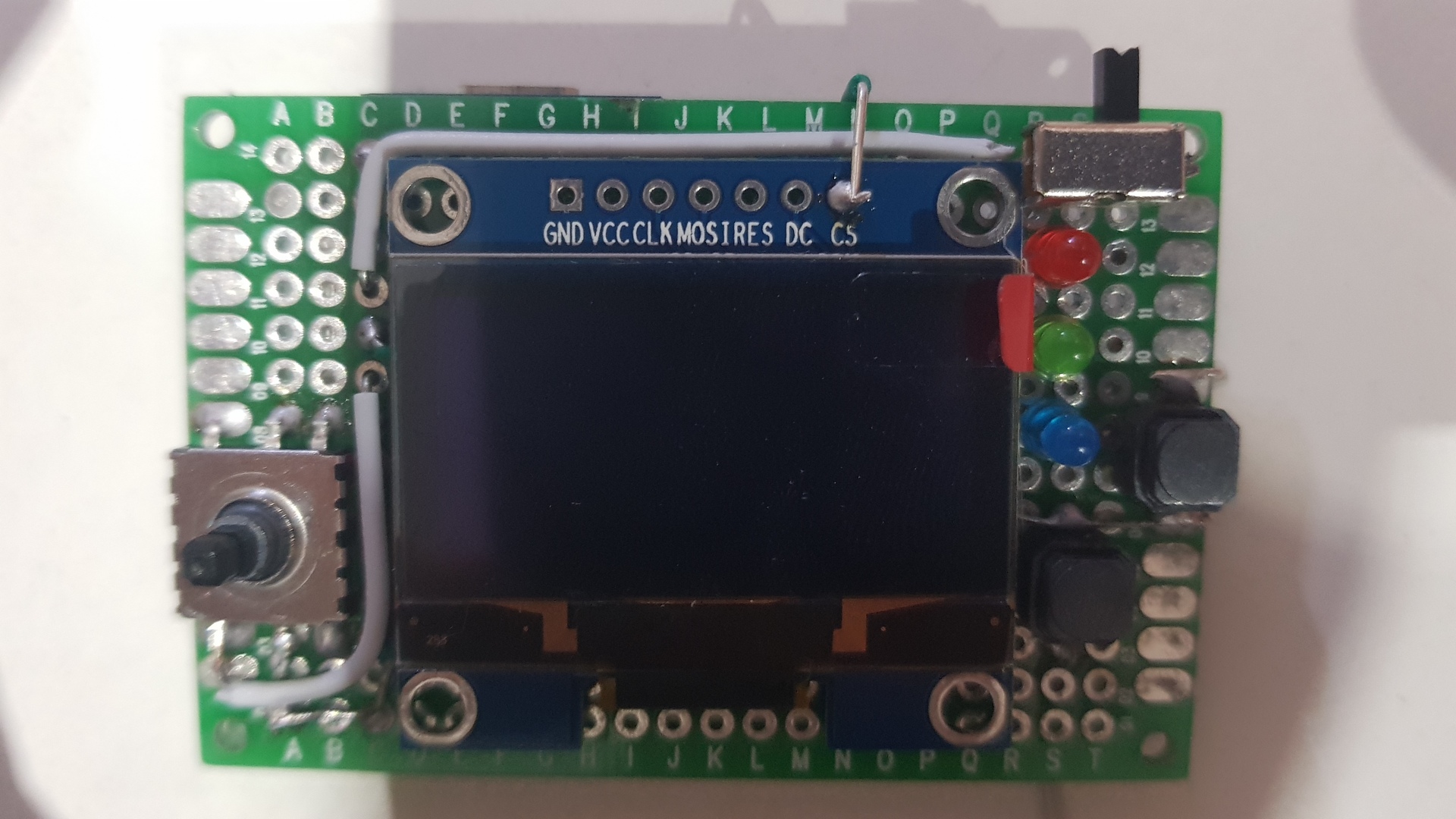
Put the screen on the center of the prototype PCB using double sided adhesive:
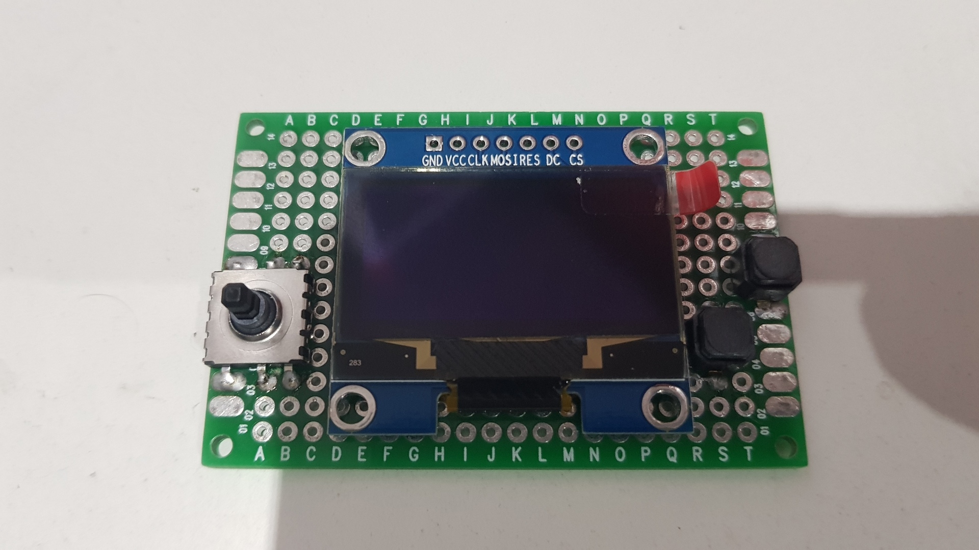
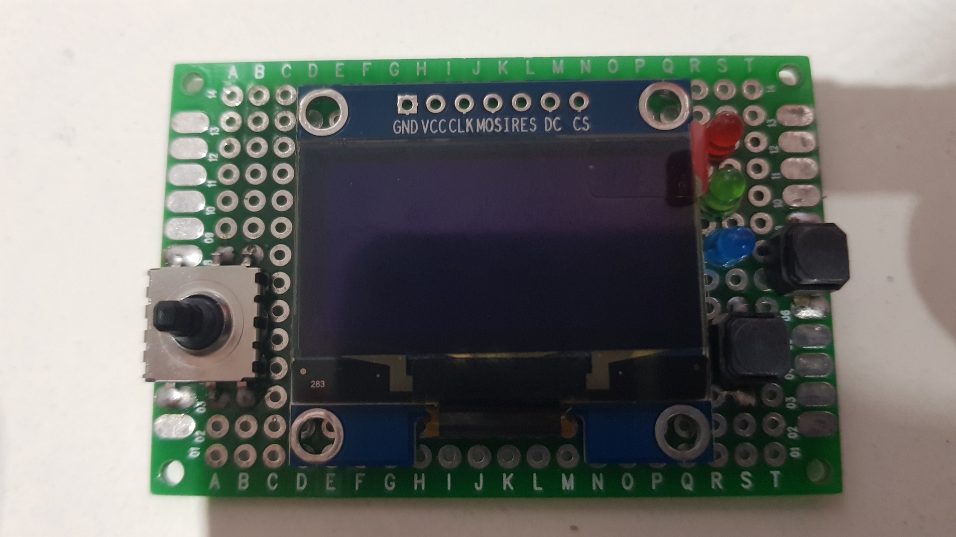
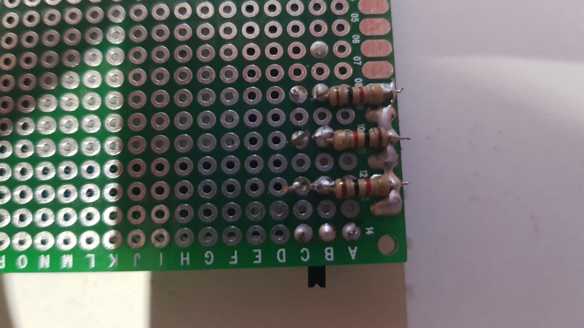
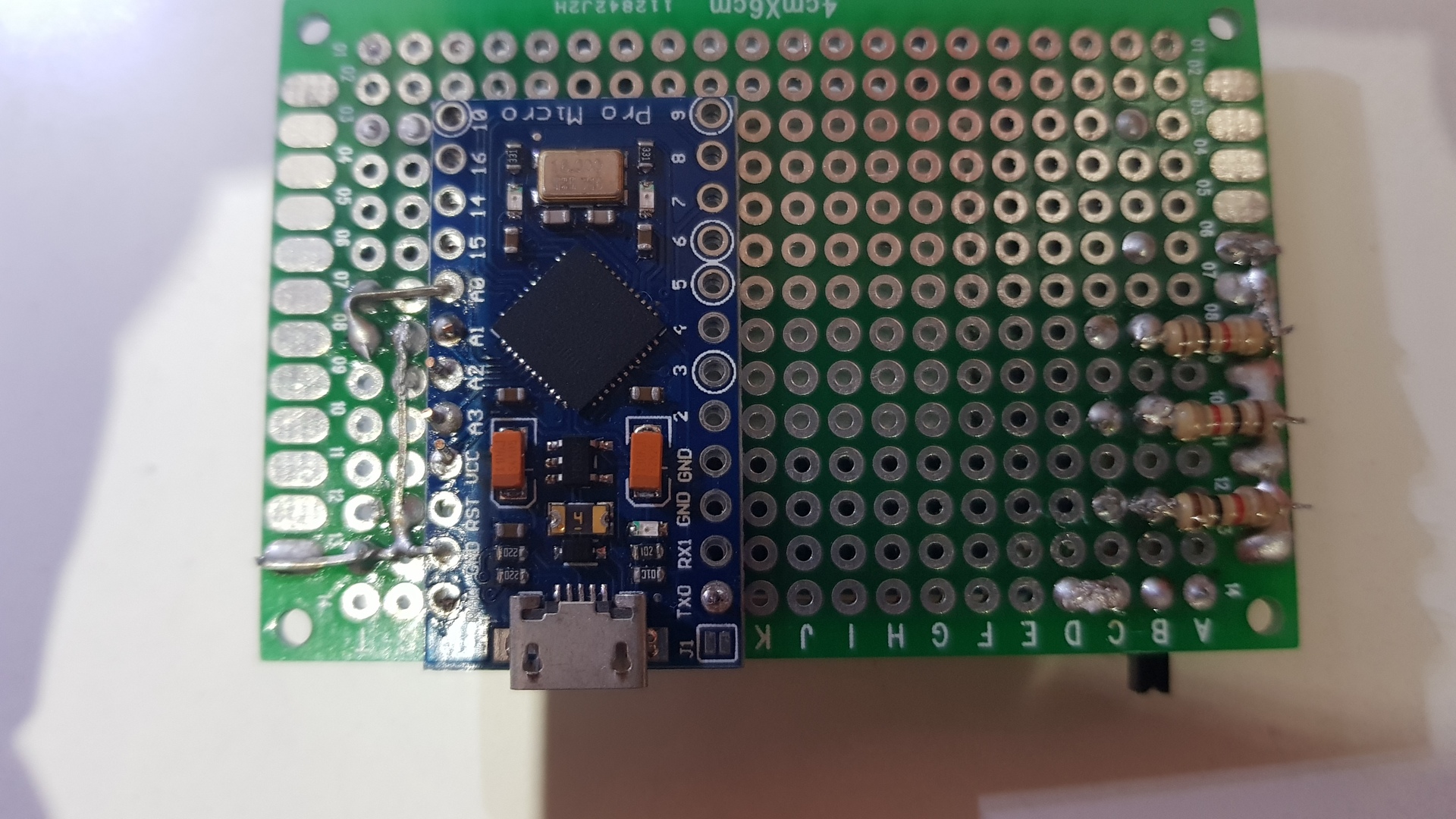
Solder the 5 ways stick, the 2 tactile buttons, the leds and the resistors (on the back) and finally the slider switch :
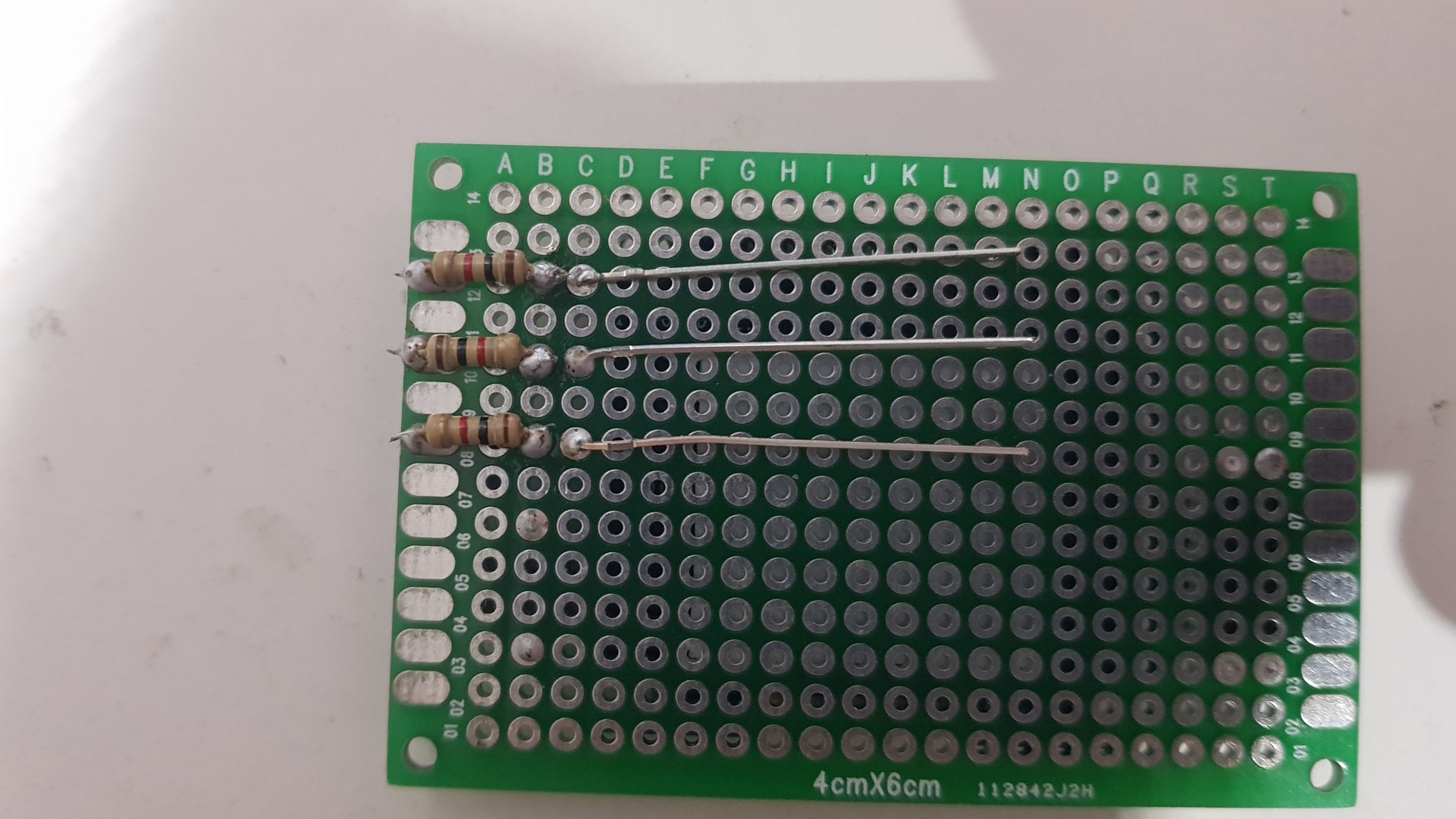
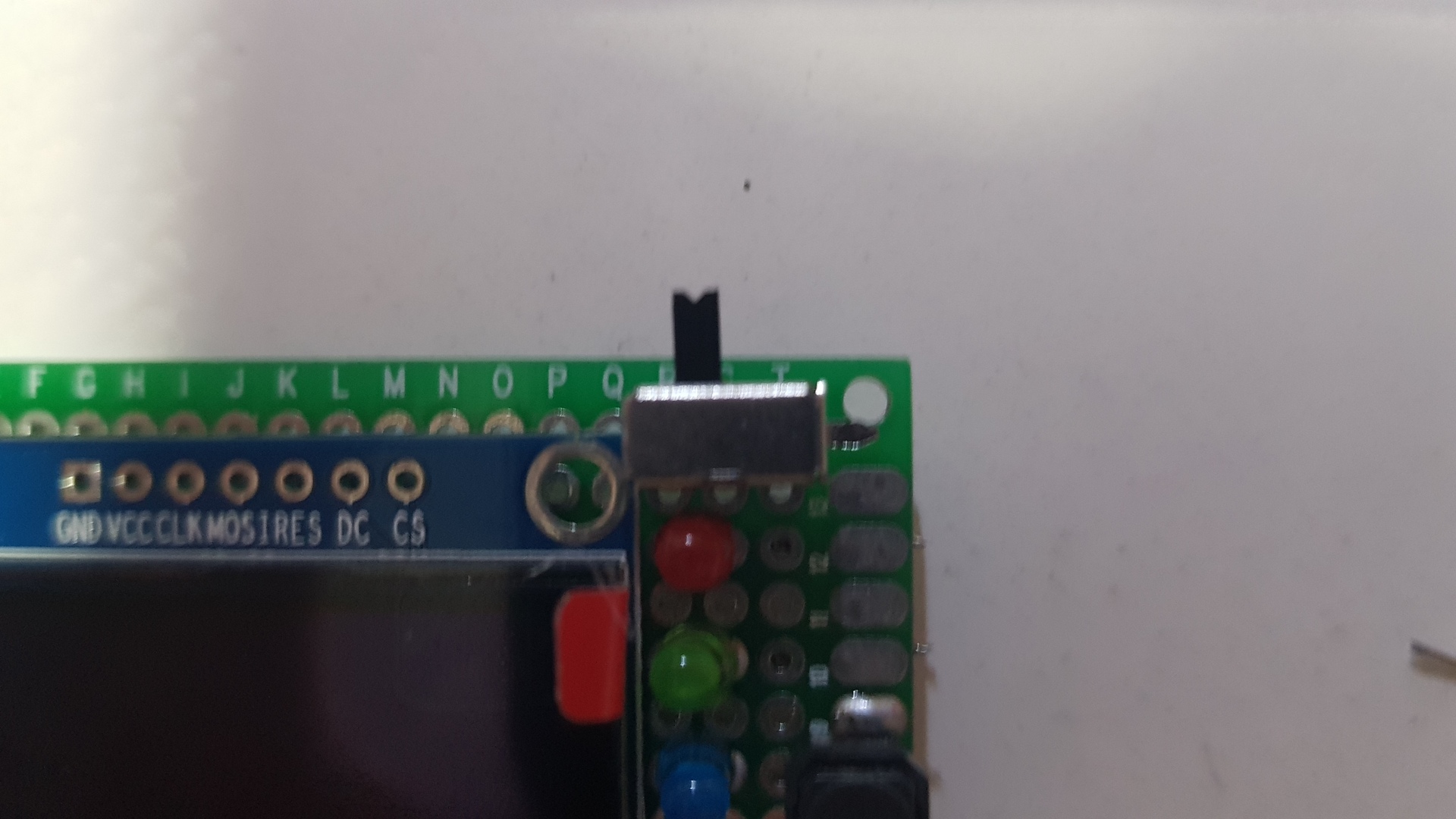
Cut (shorten) the resistors cathode, start to make a common ground with resistors and buttons (use the cathode part you just cut to easily make a solder path):
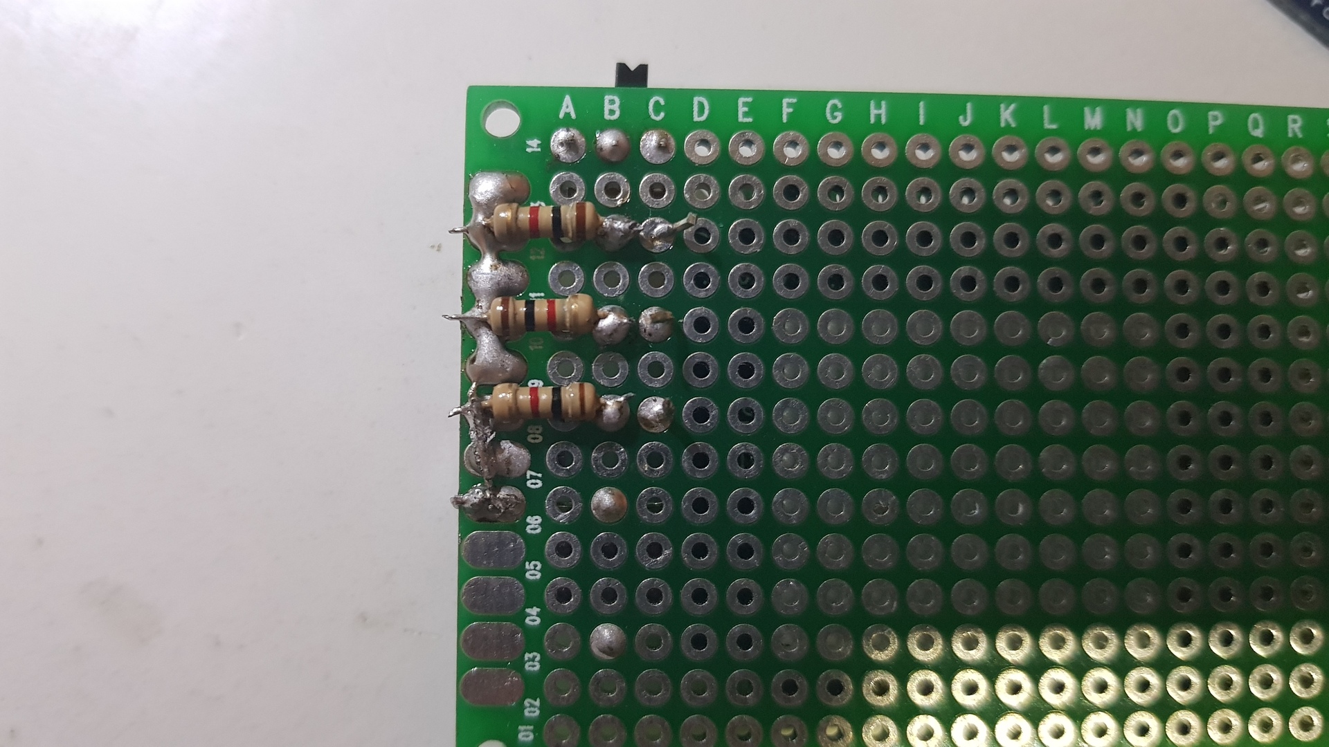
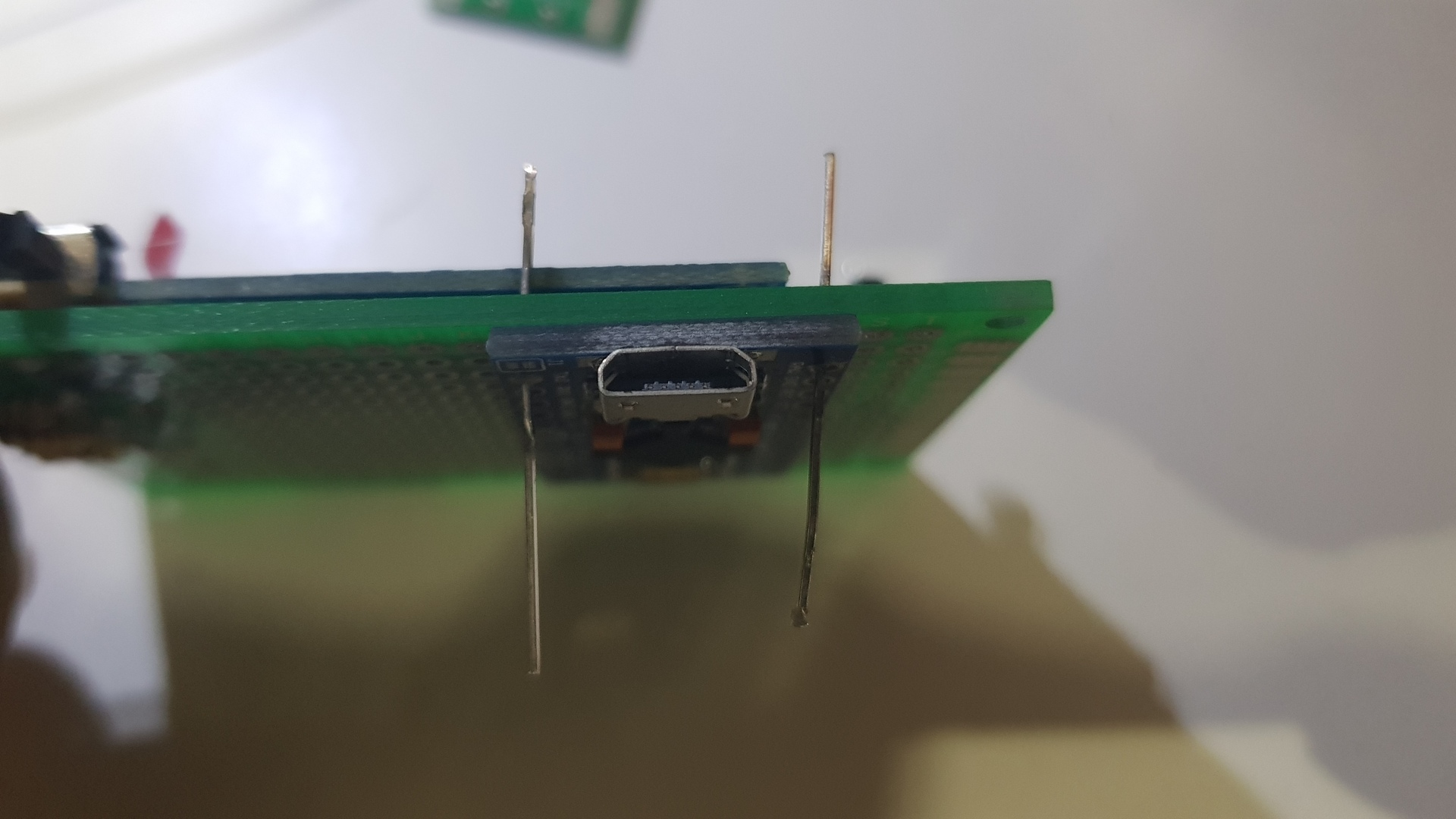
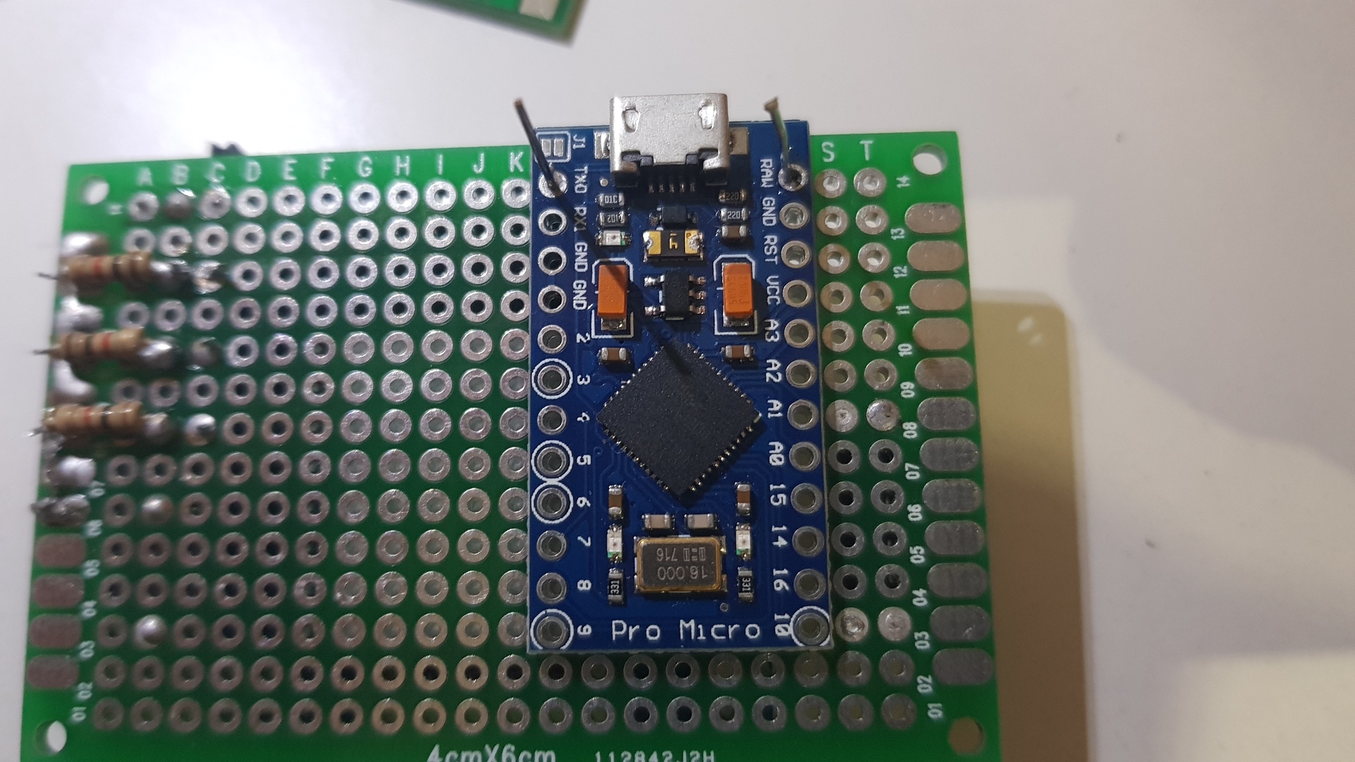
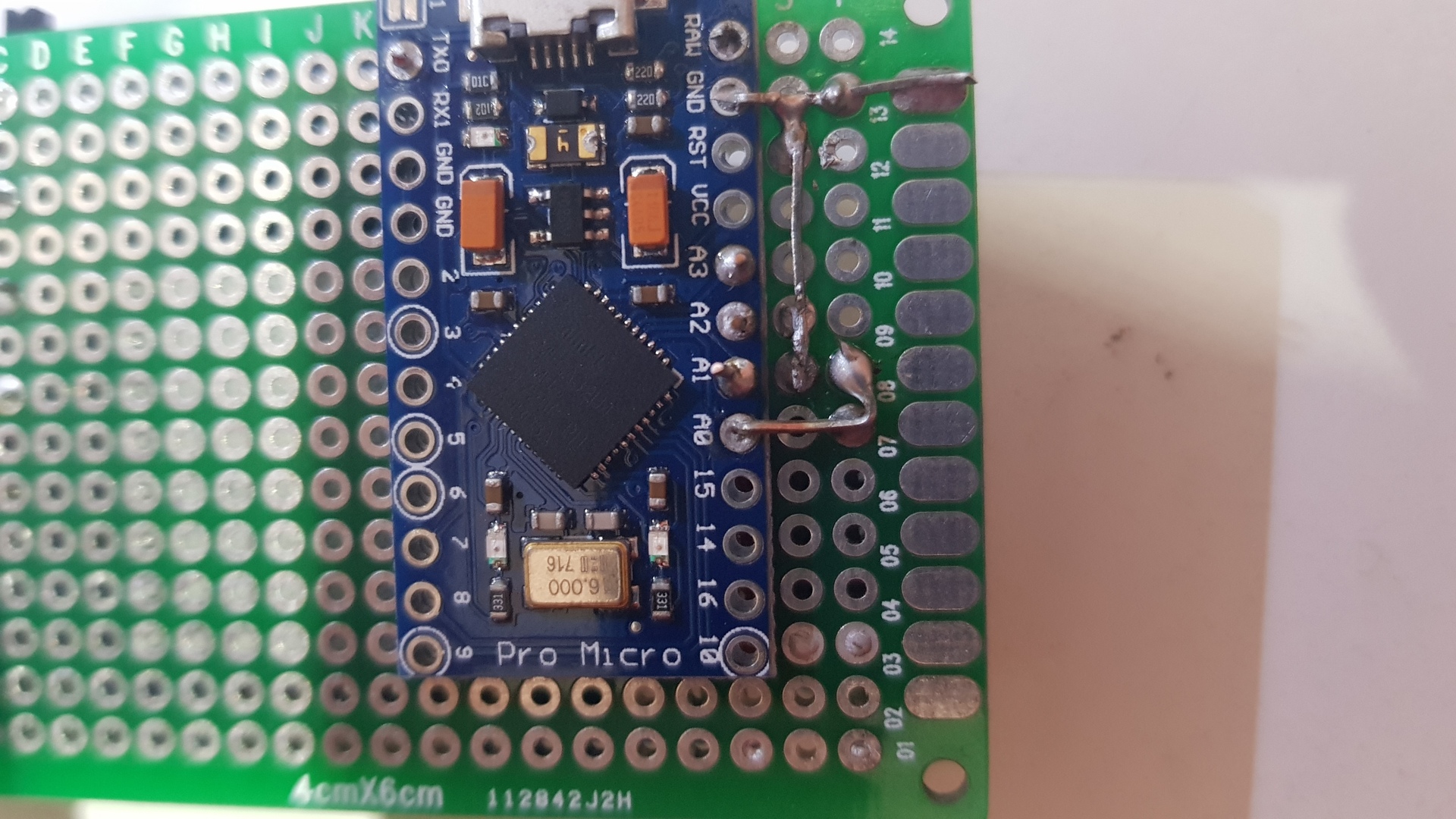
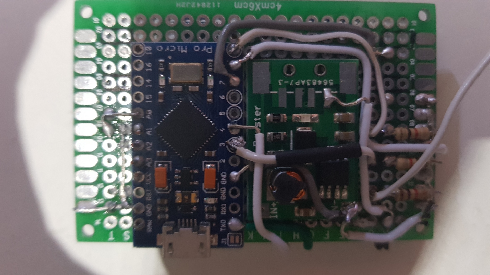
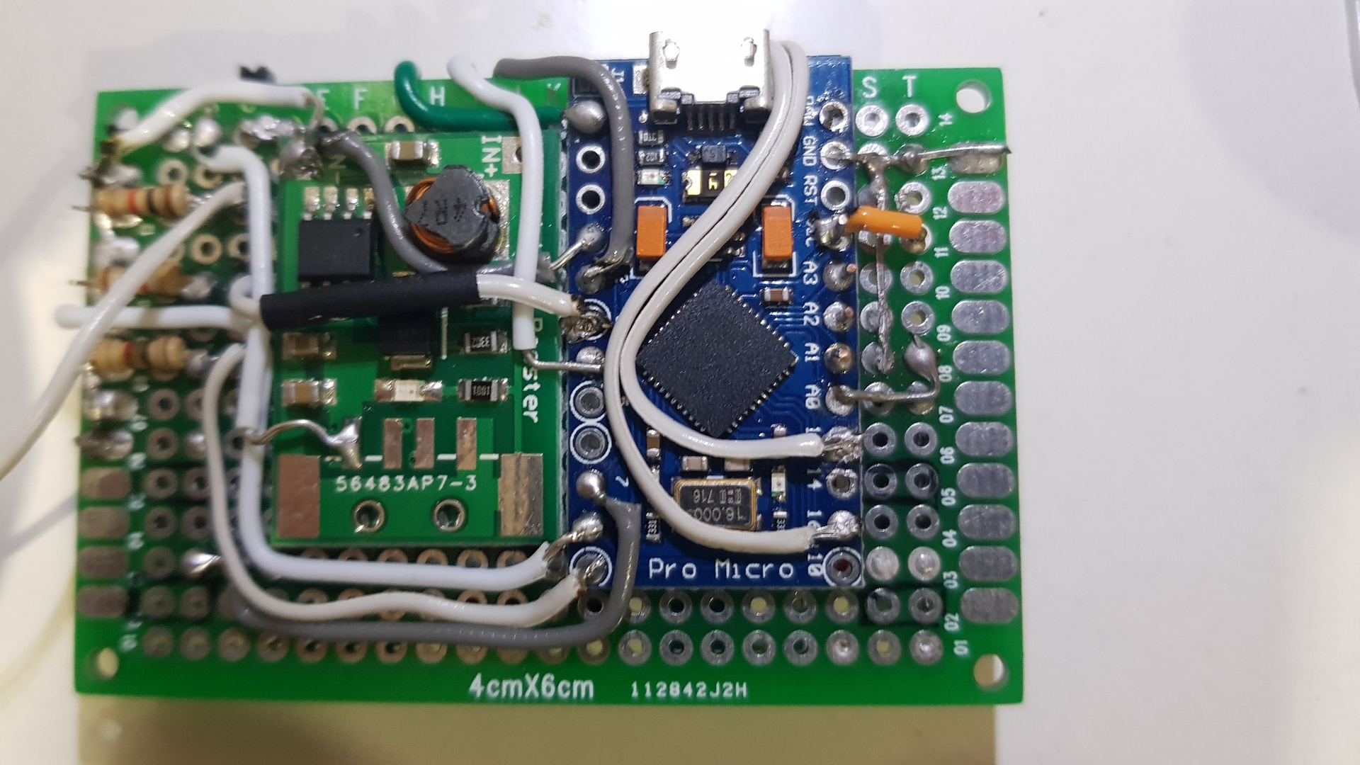
Solder the Arduino board on the back (behind the display), with the help of the resistors paws that have just been cut in the previous step and make a ground path for the 5 way switch which is on the other side :
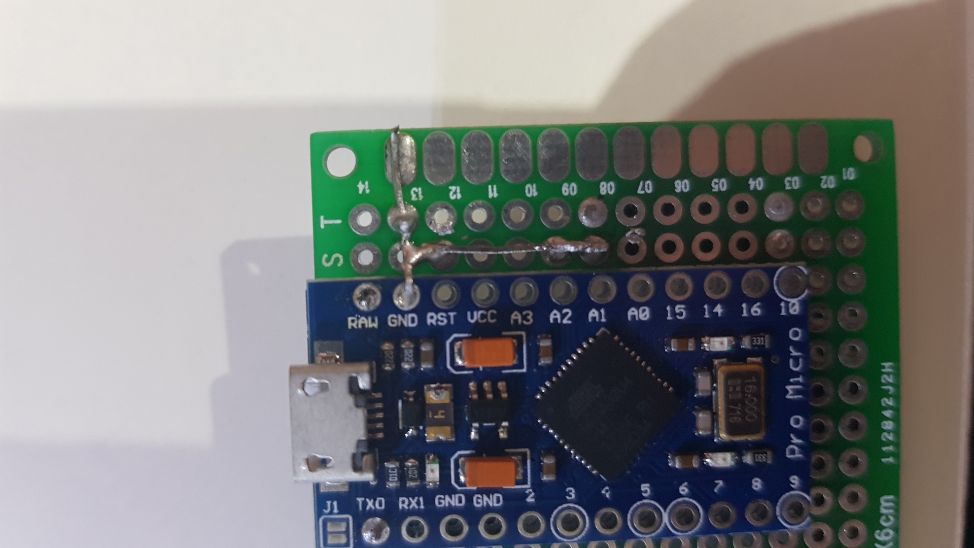
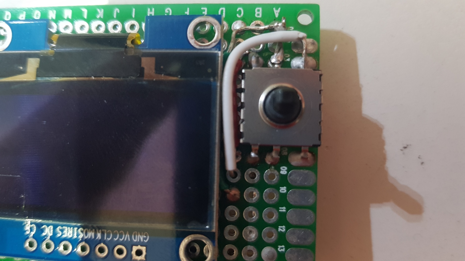
Now, wire and solder the 5 way tactile button pins to the corresponding Arduino pins (three wires are stacked, white, red and green on the photo and the fourth is soldered directly from the breadboard):
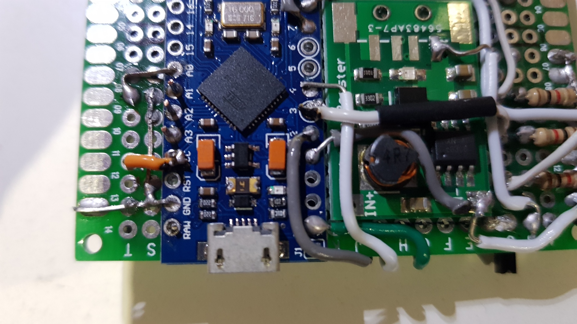
Wire the slide switch to the VCC input of the Arduino and add some ribbon cable wires to the resistors for the following step (notice the black lines I drawn to mark the future place of the step-up converted):
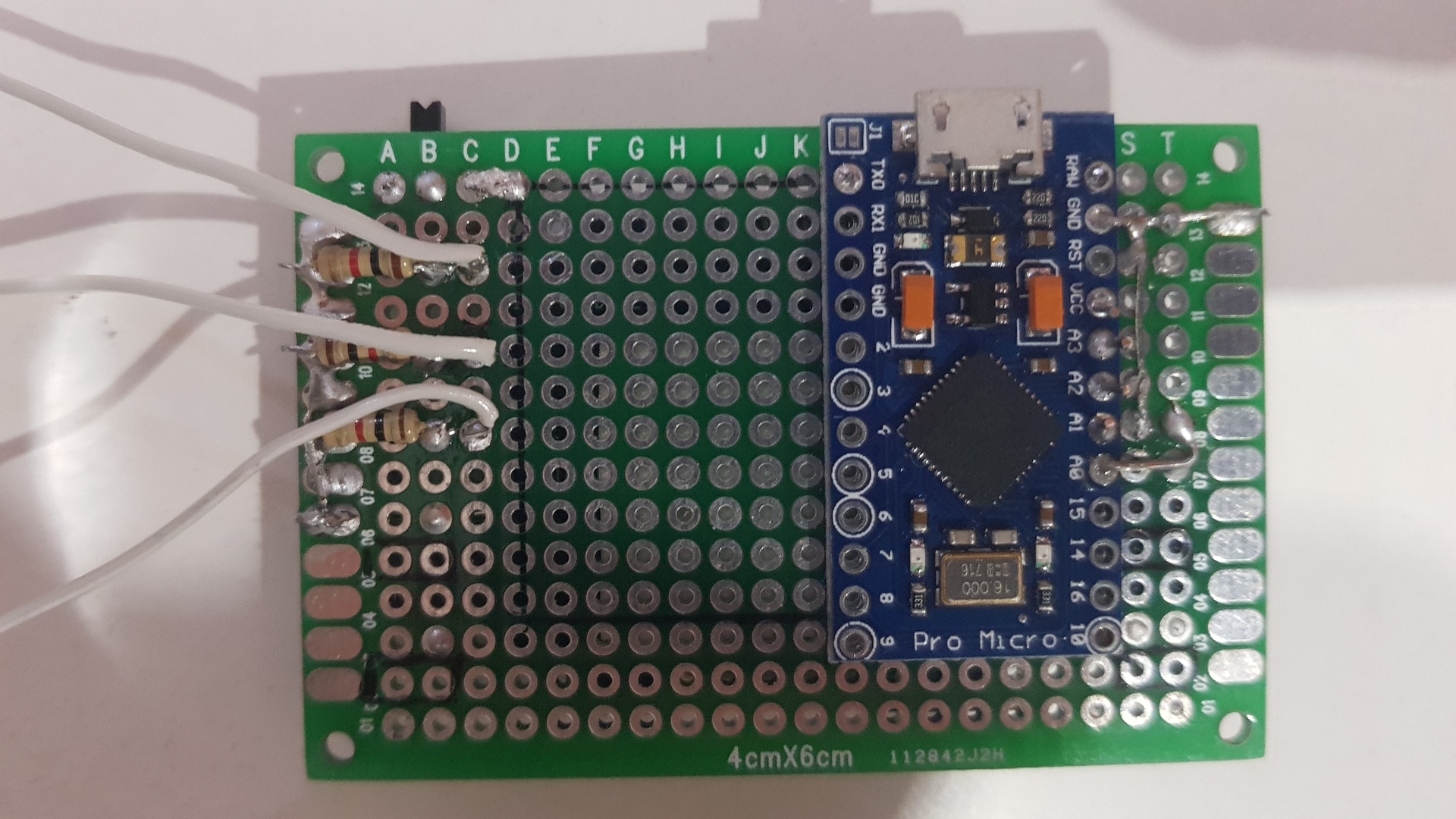
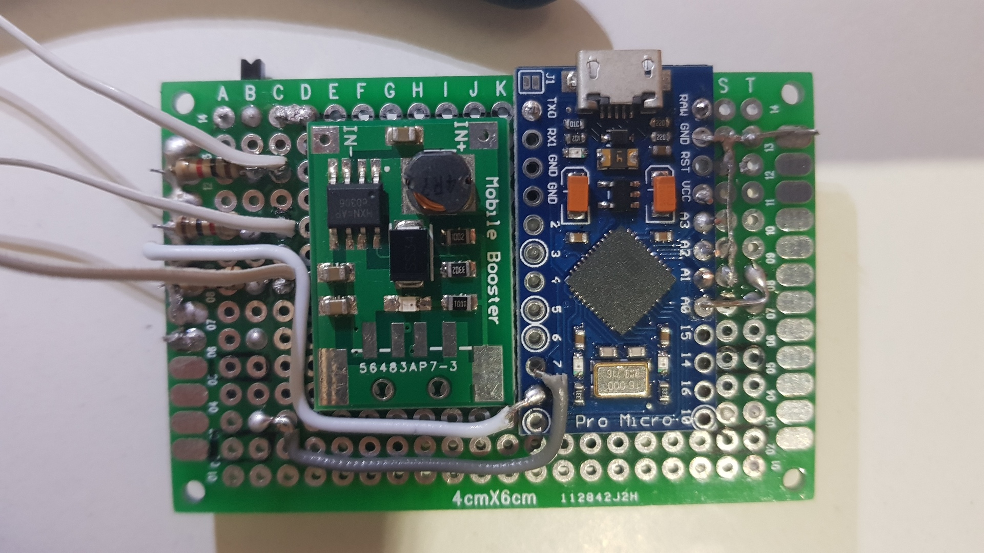
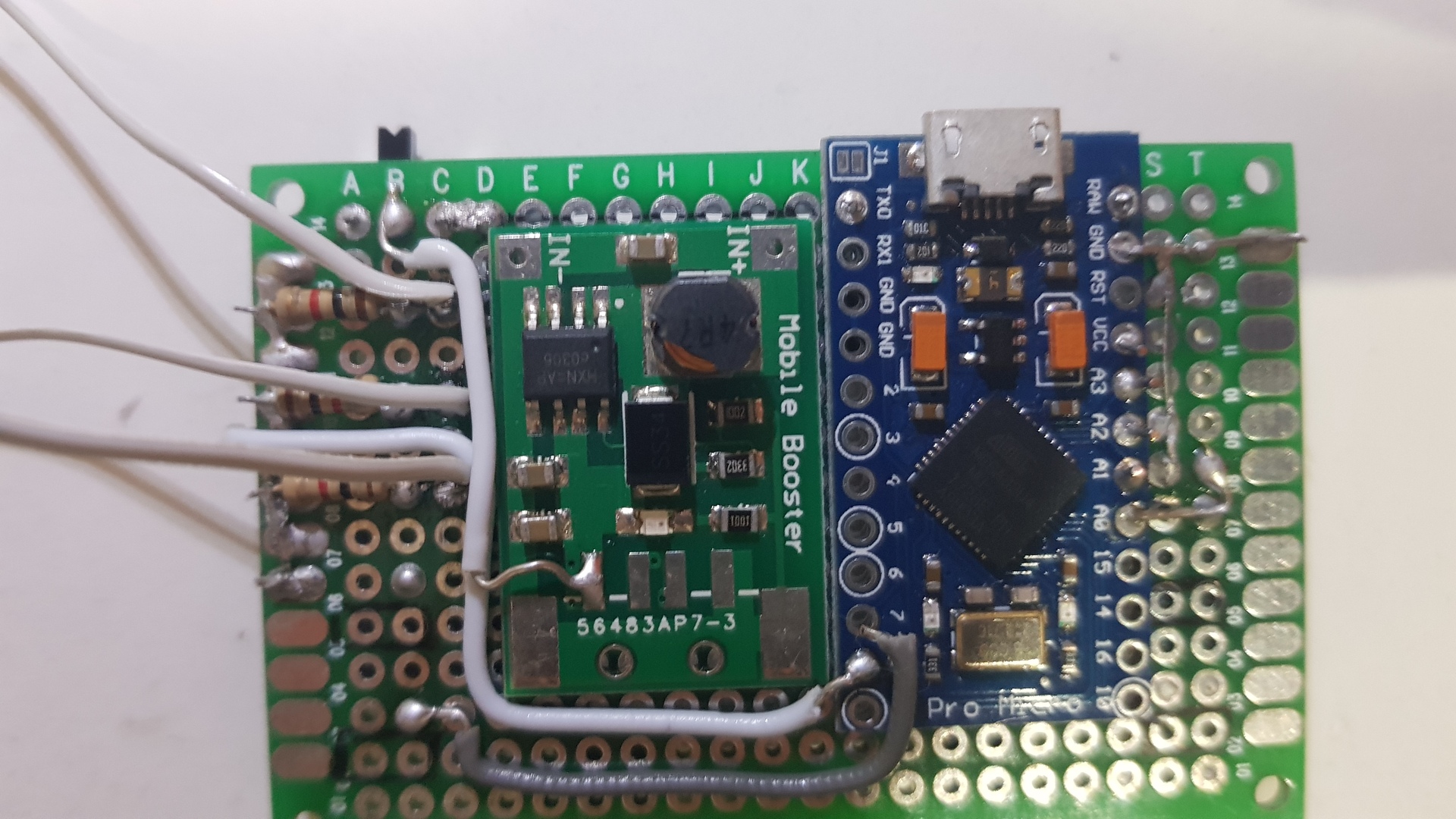
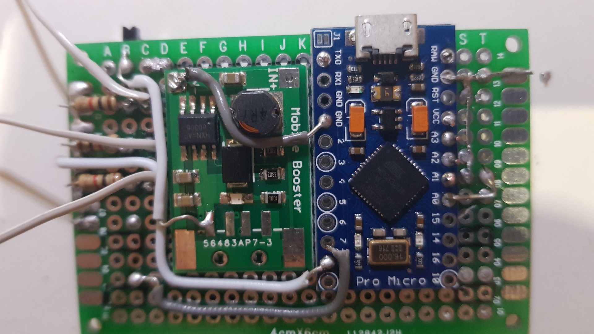
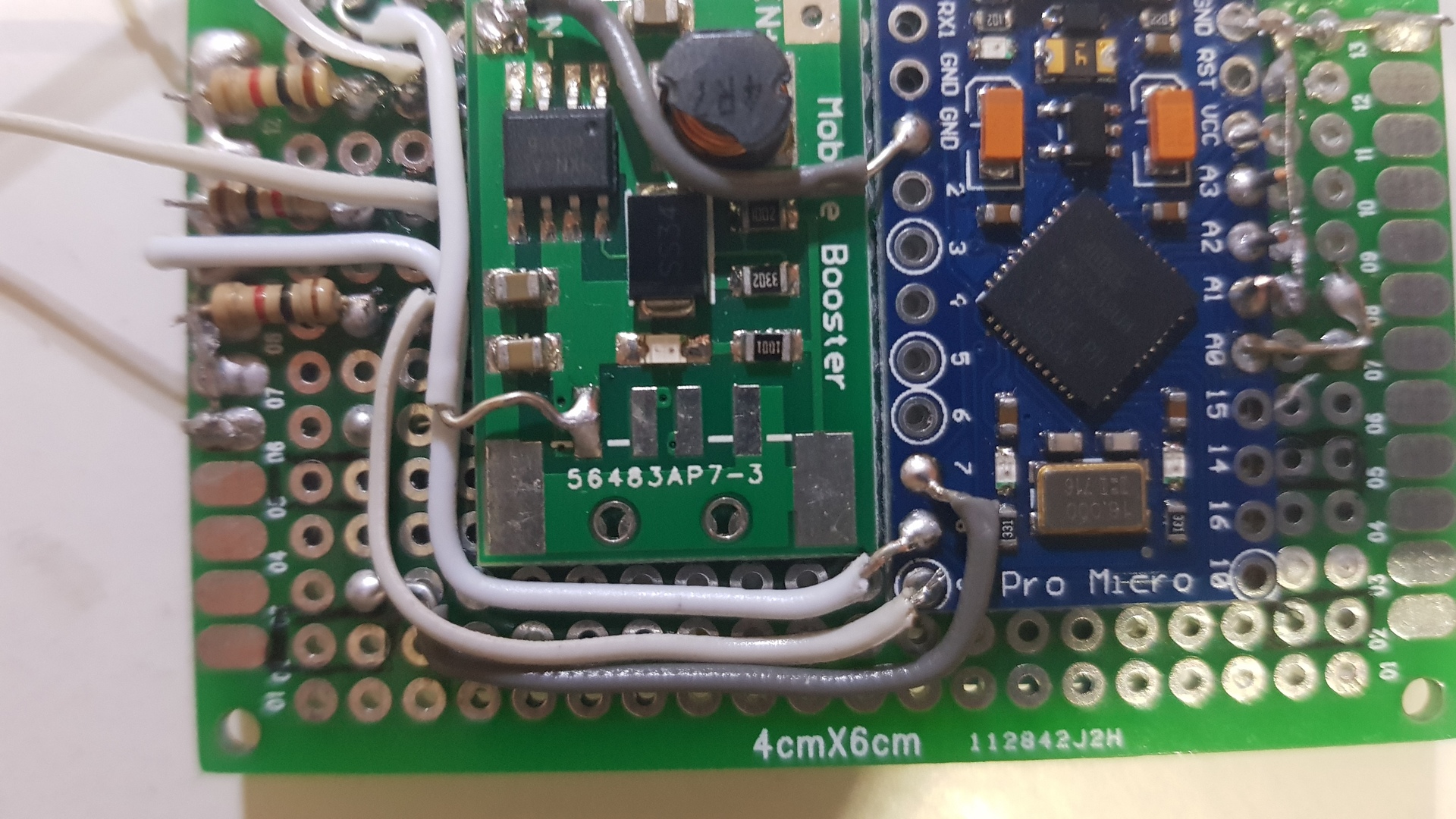
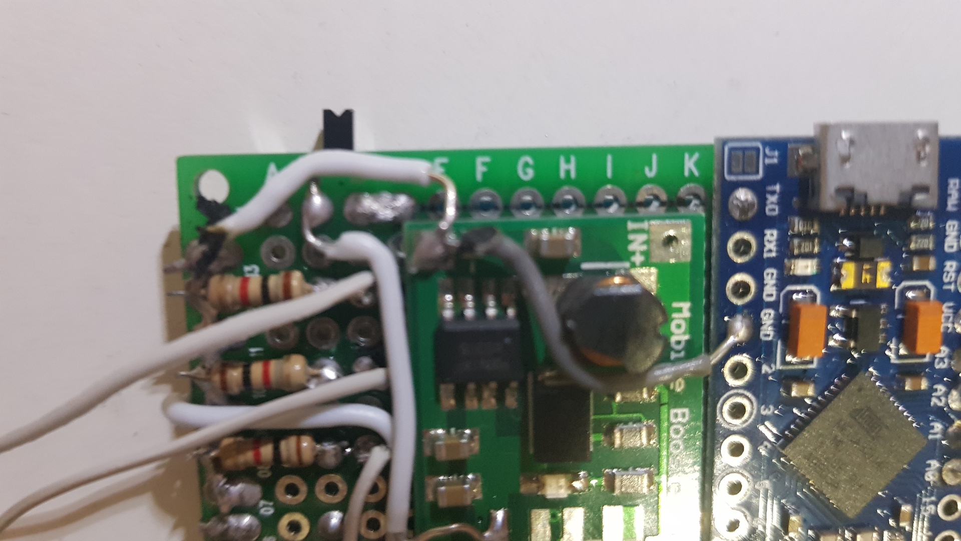
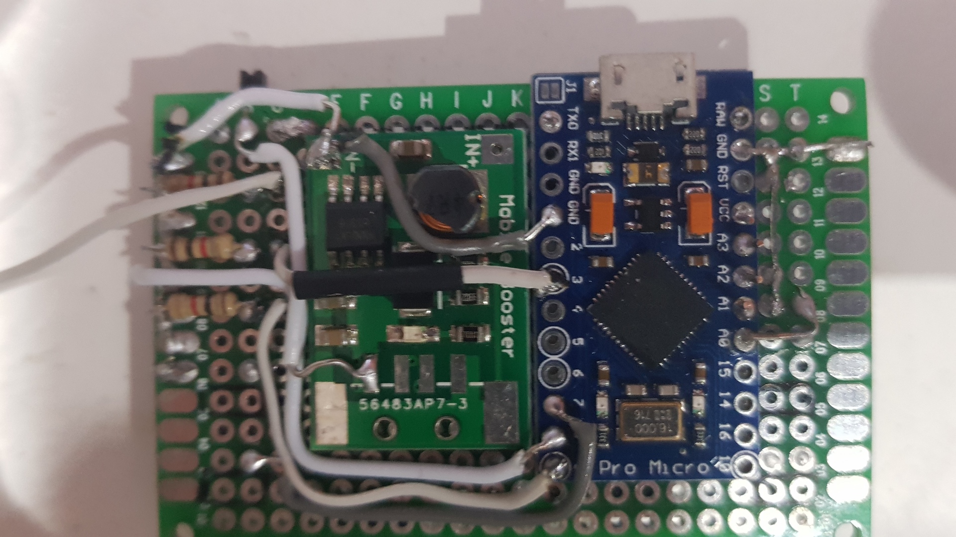
Place the step up converter, then wire the A and B buttons and one resistor to the Arduino, the slide switch to the the step up converter positive output pin and its ground pin to the a ground pin of the Arduino and to the ground path of the resistors we created in previous step (so the ground of leds and buttons is wired to the Arduino ground). Finally wire the 2nd resistor (the middle one) :
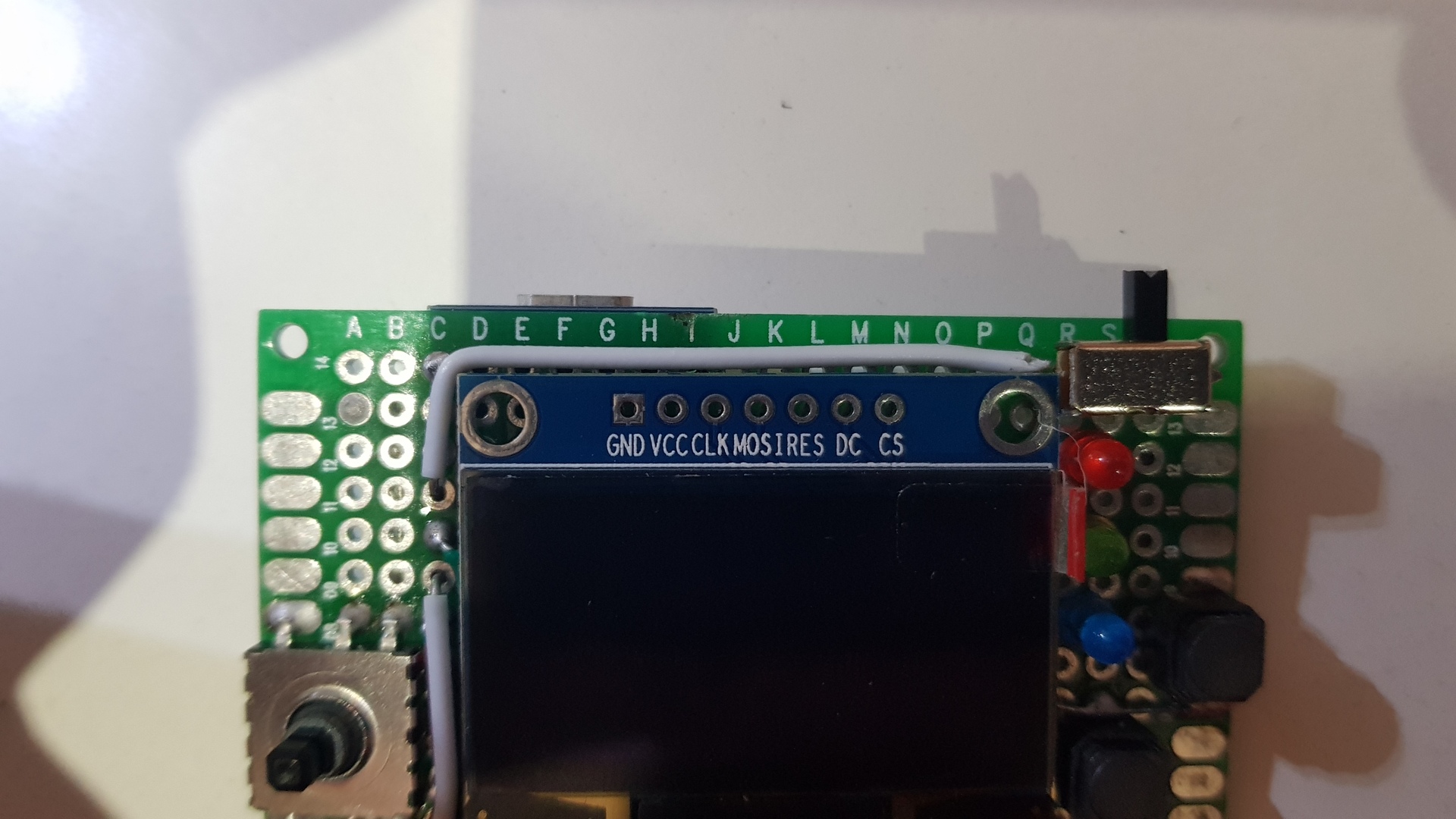
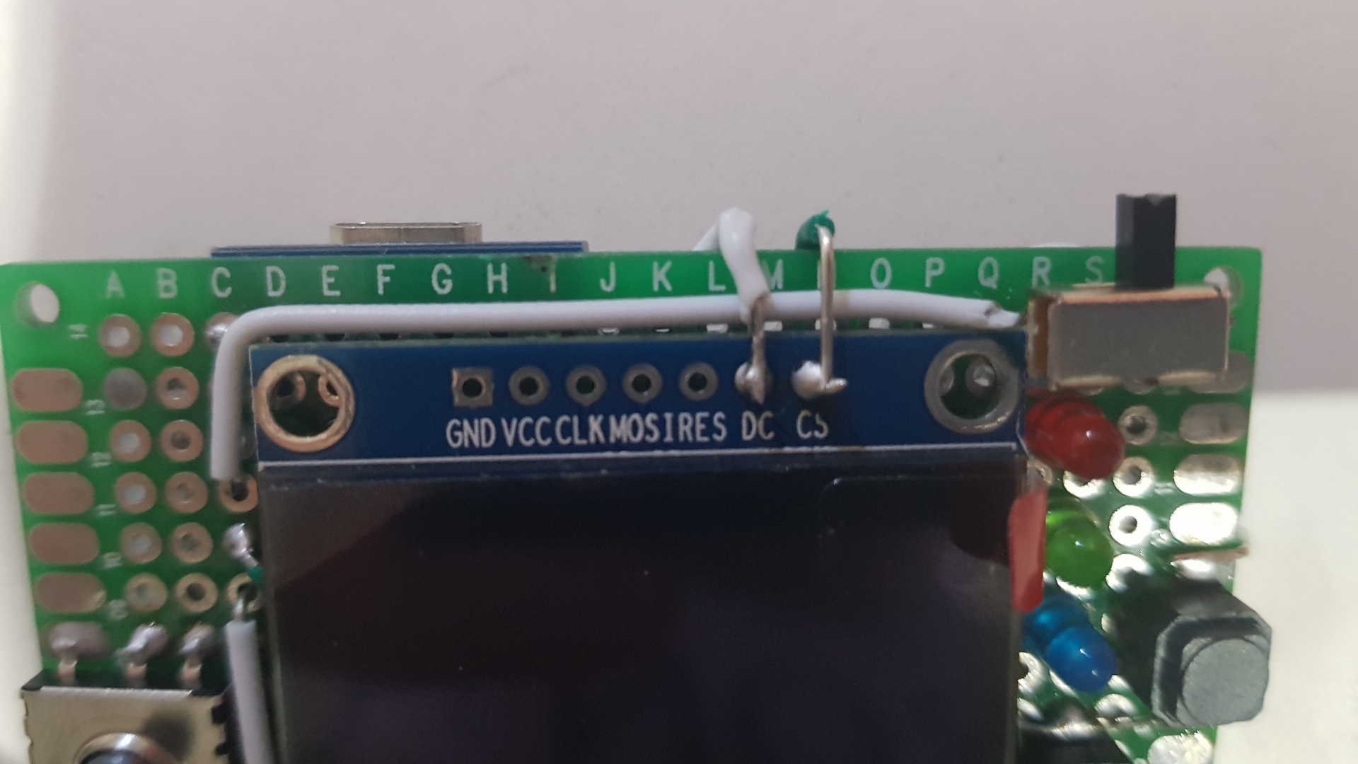
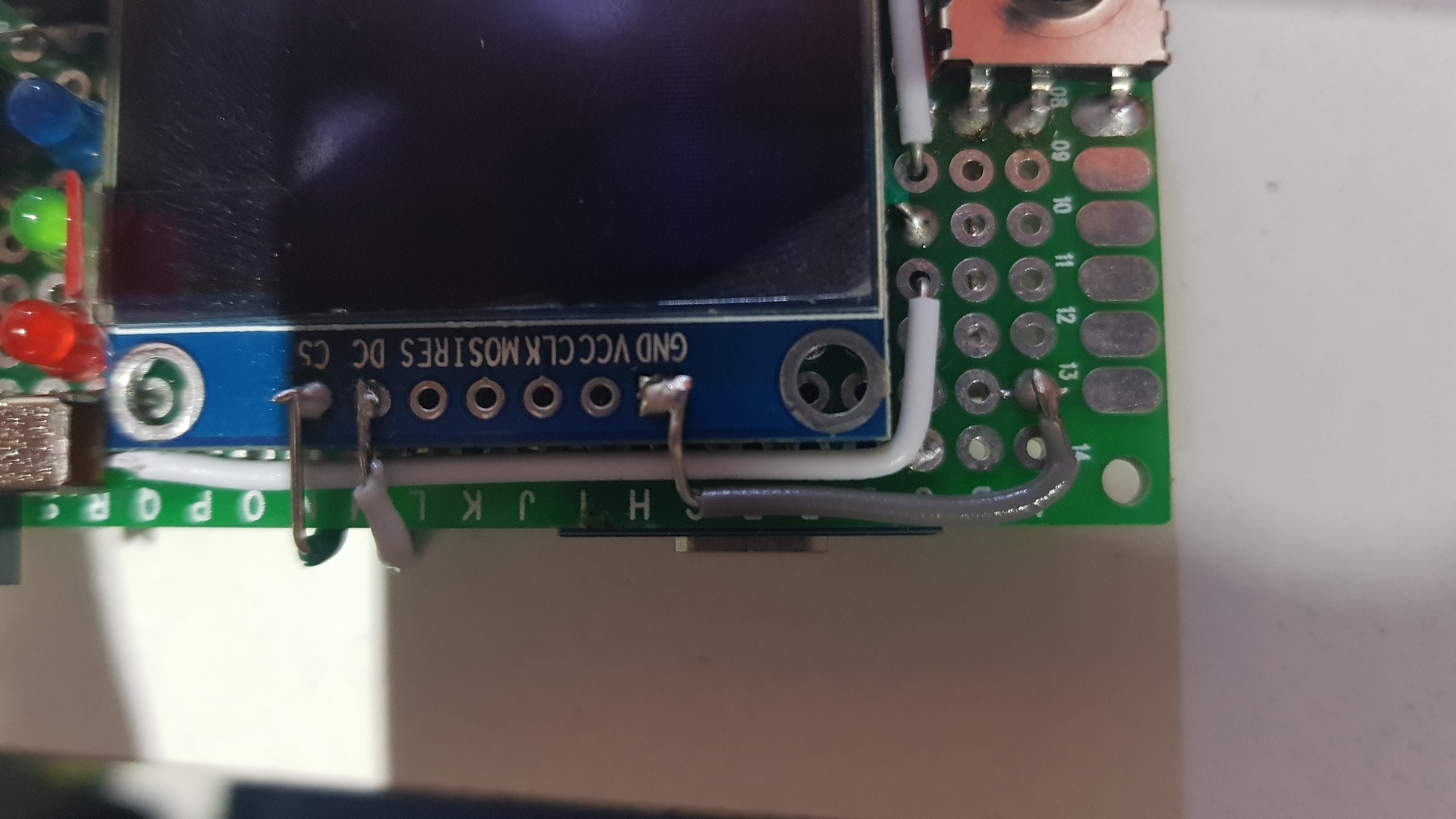
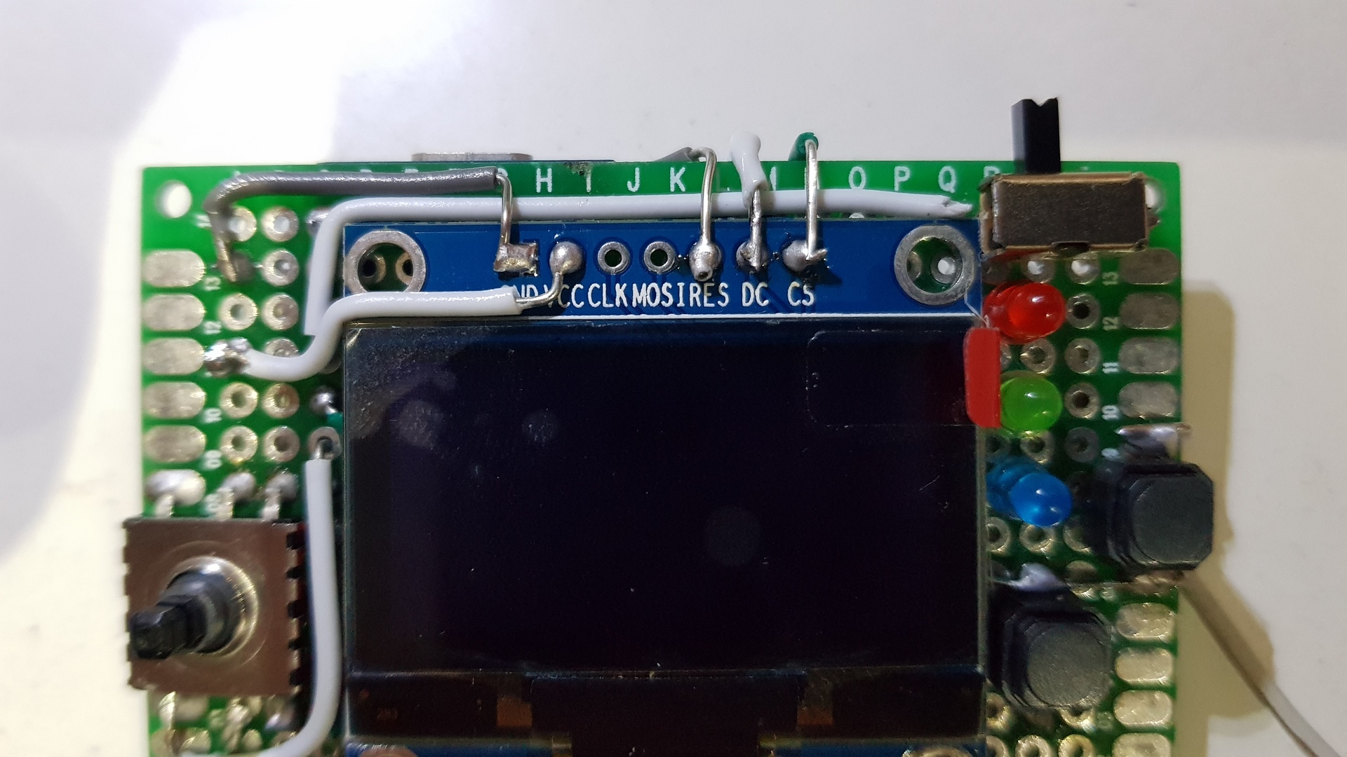
It’s time to wire the screen:
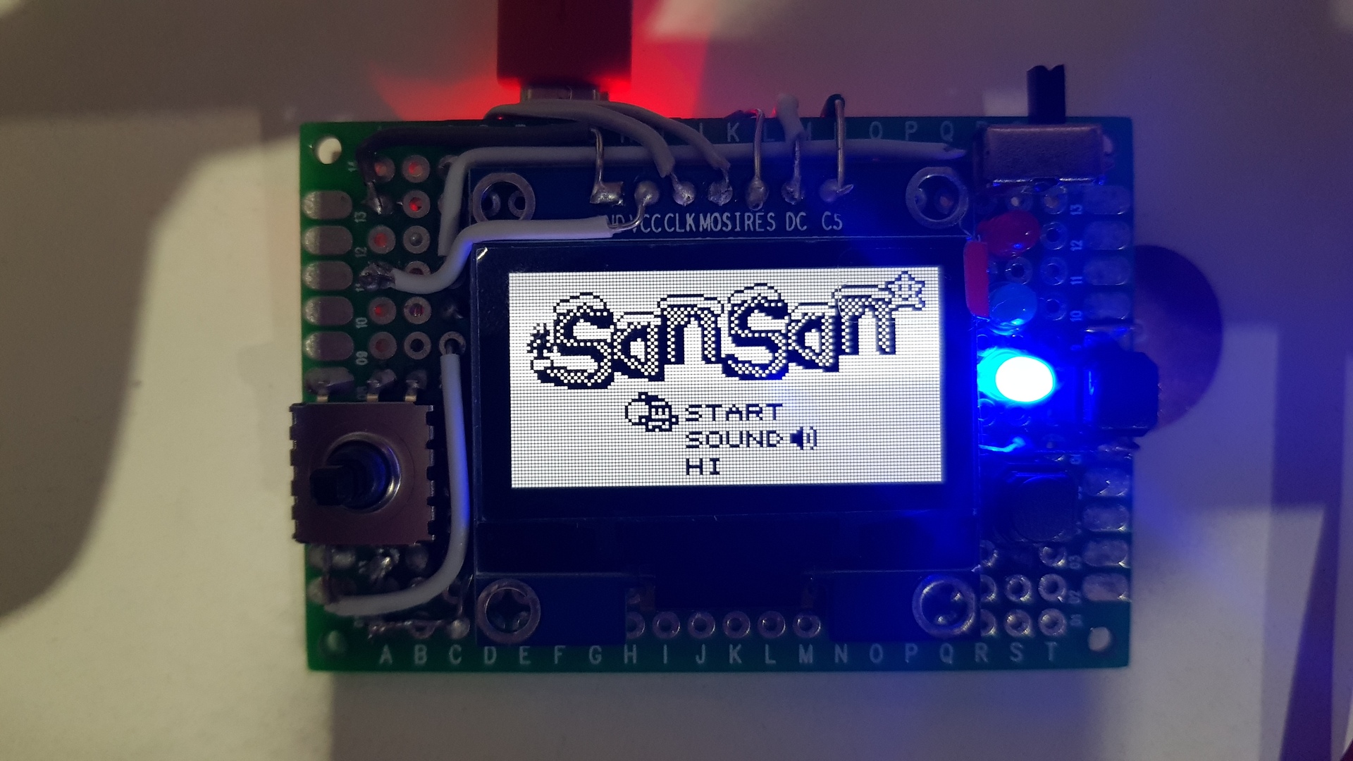
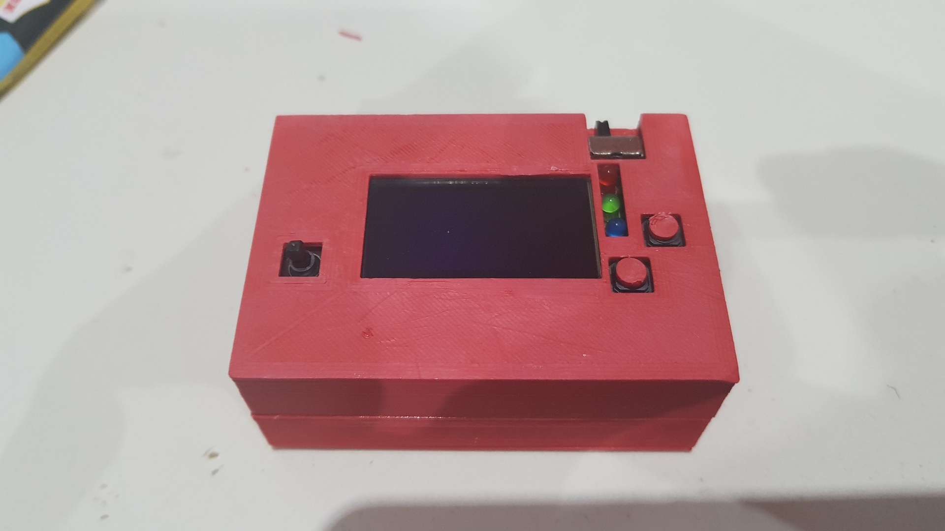
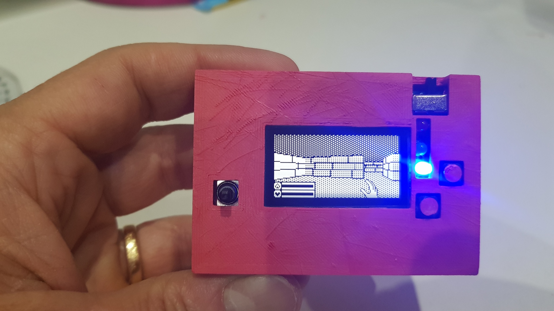
Add the piezo buzzer and put a game to check if its starts :
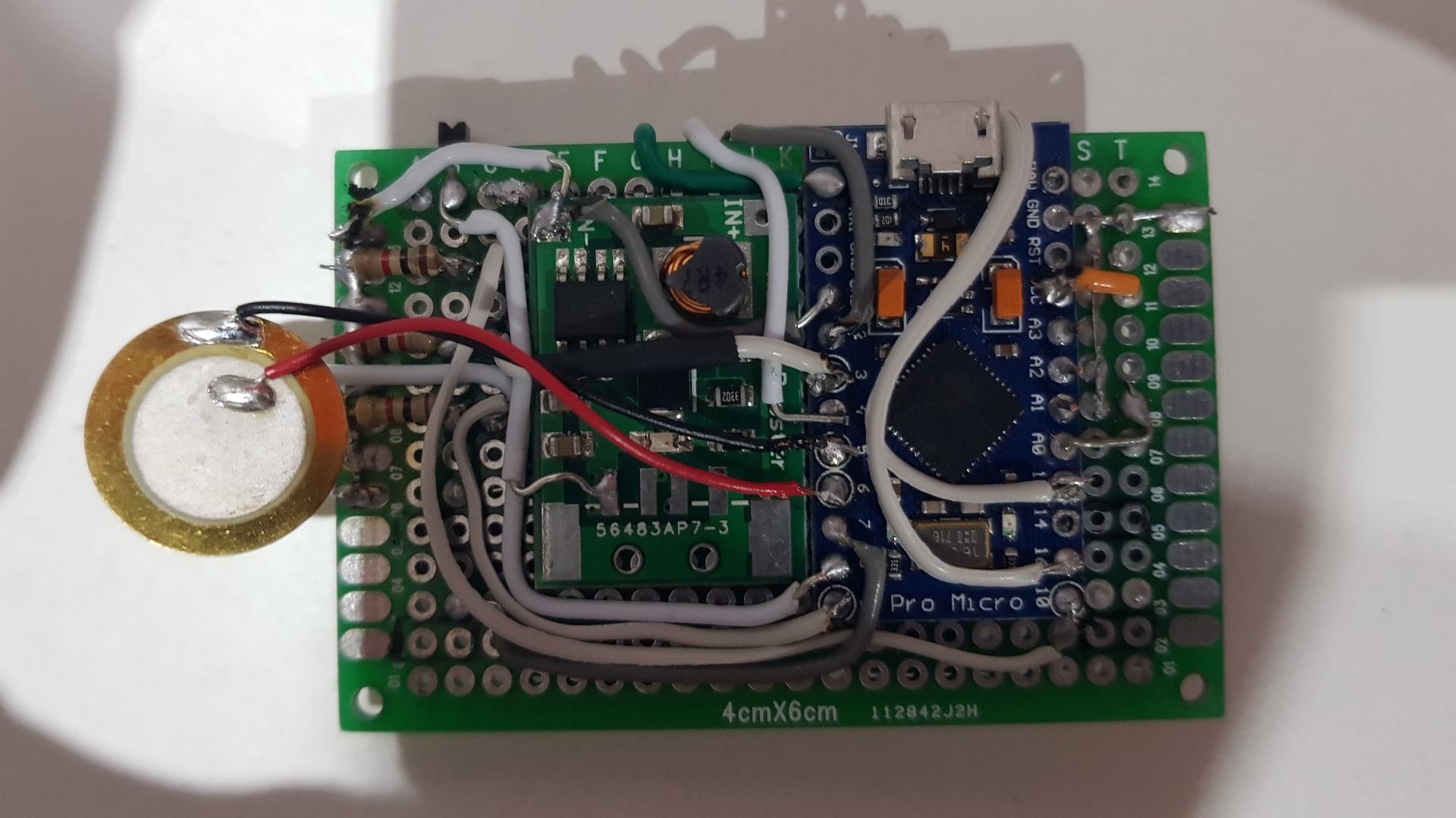
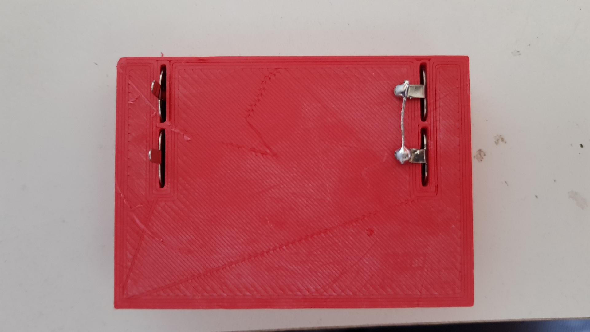
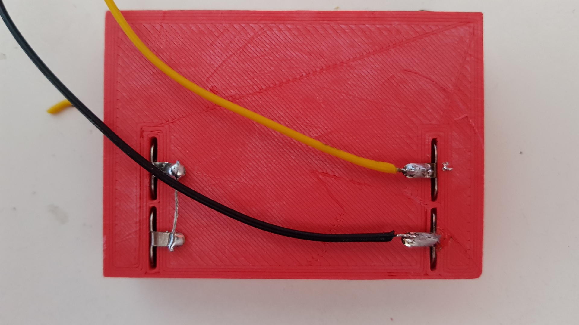
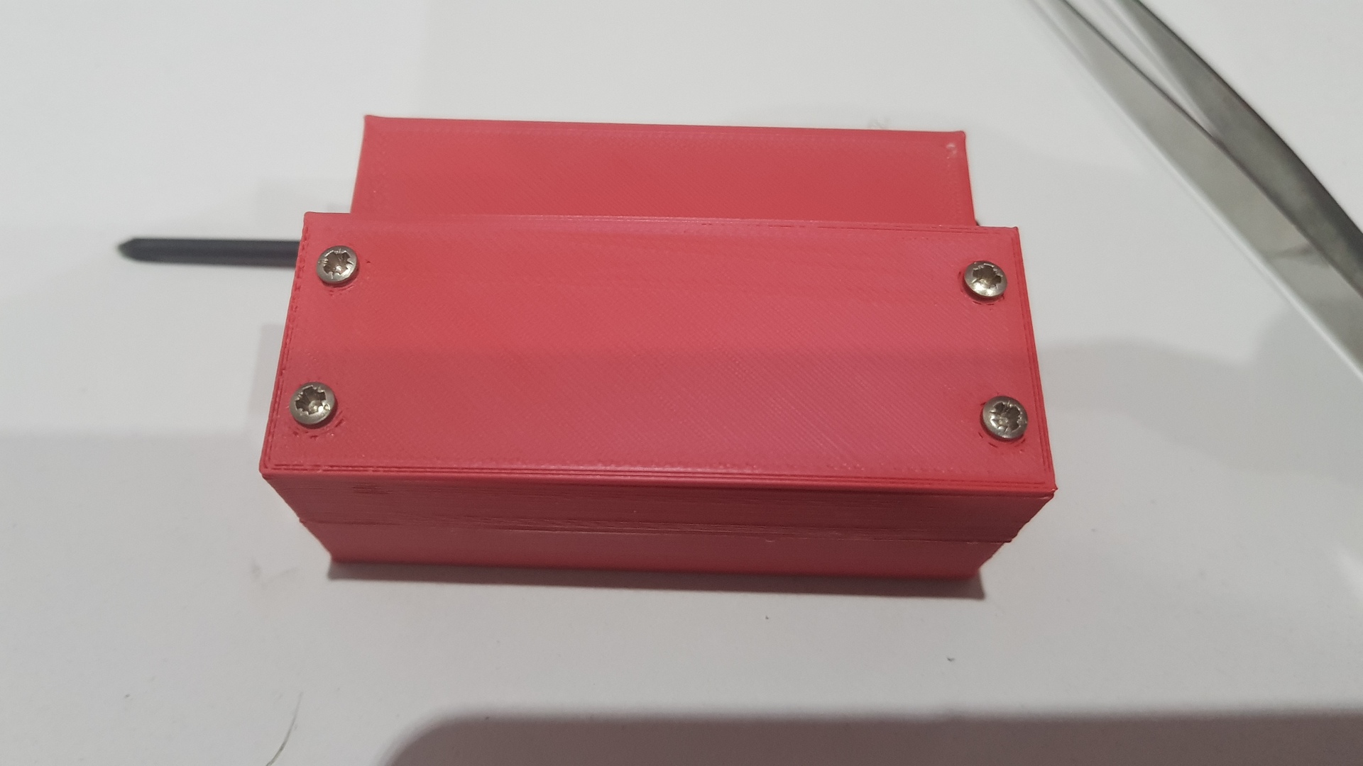
Add the battery springs and noses on the 3D printed back piece (see the link to the model at the end of the article) and solder wires:
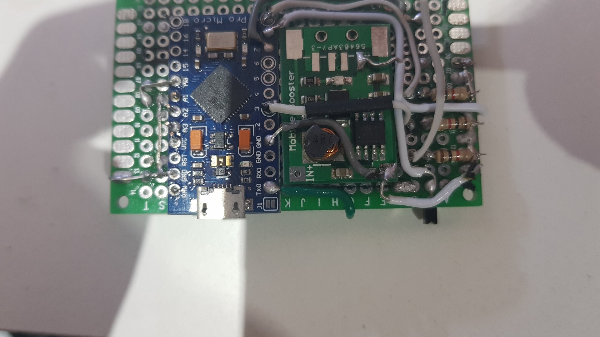
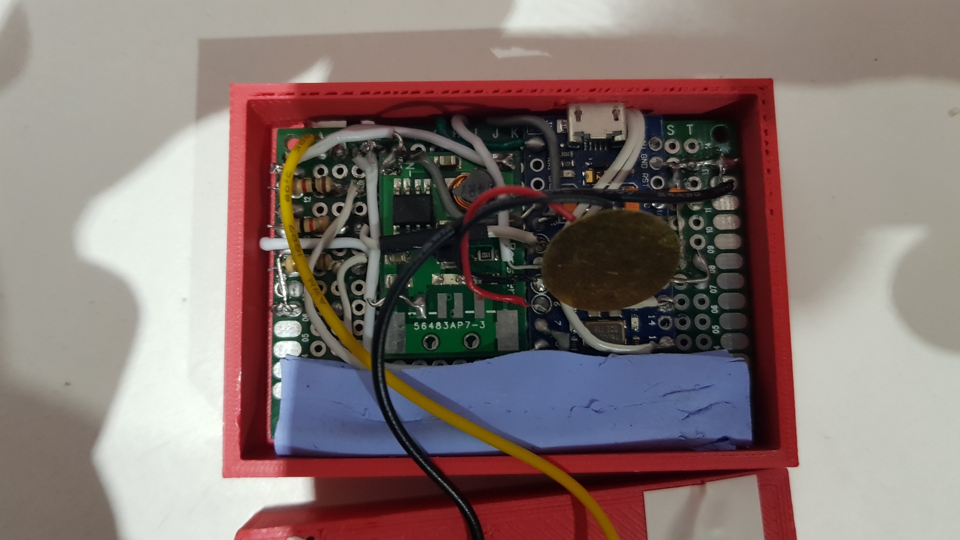
Solder battery holder wires to the step-up converted, then place the board on the case. Glue it or, as I did, block it with some thermal pad parts :
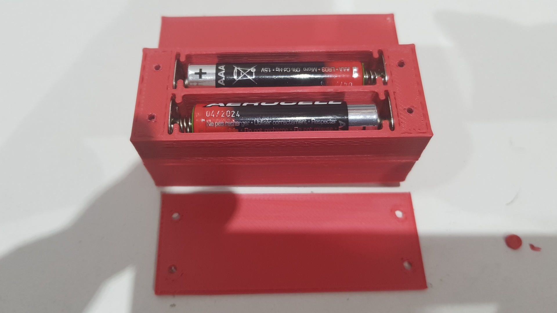
Glue the back of the case (make sure the piezo plate is touching the back of the case to get some sound), put batteries, screw the battery cover, glue the button pads and… switch on !
Uploading a Game
Install the Arduino framework alternative on the Arduino IDE by Following the guide on github : https://github.com/MrBlinky/Arduboy-homemade-package/blob/master/README.md
Then just get the source code of a game, remove batteries, plug the micro-usb cable in the Arduino.
Go to the Tools menu and choose :
- Board : “Home made arduboy”
- Based on : “Sparkfun Pro Micro 5v – alternate wiring”
- Code : “Arduboy optimized core
- Display : “SH1106”
- Bootloader : “original (caterina)”
- Flash select : “Pin0/D2/Rx (Recommended)”
Upload the sketch
3D model to print
The case was made with freecad, sliced with Cura (4.1) and printed with an Anycubic I3 Mega.
The sources files are on Thingiverse (stl, and freecad files) https://www.thingiverse.com/thing:3774618
Hi there , i really like this version .. and this i s what i want to build. Do you maybe have a good schematic ? because im a beginner. i dont know your photos.. looks great but i cant figure out the pins.. DO YOU HAVE A FRITZING? OR SIMILAR OR CAN YOU MAKE IT THE SCHEMATICS ? but like you have it .with 5 way schematic and mosi display..
Sorry for the delay. I’ve no schematics, but you should find what you need here : https://github.com/MrBlinky/Arduboy-homemade-package/blob/master/README.md
Hi! Thanks for sharing this! My Arduboy parts have been gathering dust all this time due to me loosing interest because SSD1306 Oled is too tiny. But Mr.Blinky (big thanks Mr.Blinky) made the SH1106 work for the Arduboy… now I got my SH1106 Arduboy… Thank you!