Homemade mini Visual Pinball system
It has been a long time since I wanted to build my own Visual Pinball cabinet. I finally took the time, but as I don’t have enough space for a “standard” sized pinball, I made a miniature one, a kind of bartop pinball.
This is the story of my build, not exactly a recipe, but it may inspire anyone who is thinking to build one…
Hardware requirements
Tools & Materials
So far, here is the main things I used for this build :
- Chipboard wood, 10mm. I used one 80x160cm board. Any other type of wood could have been used, but I found this kind of wood feels more authentic when painted.
- Plastic brackets
- Pine wood cleats
- Various wood skrews
- Circular saw
- Jigsaw
- 3 x 400ml white spray paint (satin finish)
- A bit ofbBlack spray paint
PC Hardware
The hardware I used is by far not the most powerfull, but it’s enough to run all the pinball tables I tested at 60 fps in (near) Full-HD resolution, while staying cool and quiet.
- Playfield display : CHIMEI CMV 222H, 22″, 1680×1050
- Backglass display : Dell 1708FP, 17″, 1280×1024
- Motherboard : ASRock B560M-ITX/ac
- 2 x 4Gb DDR4 3200 ram modules (Kingston hyperX fury)
- Kingston A2000 NVMe SSD M.2, 500GB (a 250 would have been enough)
- Pentium G6400
- Zotac GeForce GTX 1050 TI Mini (4 Gb)
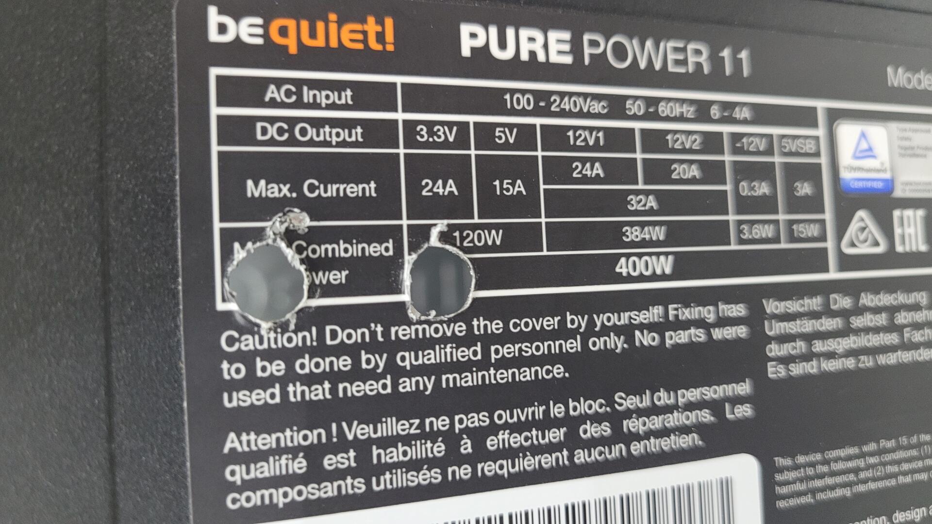
- be quiet! Pure Power 11 (400 W)
Other hardware parts
- 7 backlit Sanwa arcade buttons, 4 blues and 3 whites (33mm)
- 1 big blue backlit button (45mm)
- 1 small push button for ATX power-on (10mm)
- Usb ports for dashboard panel
- A true pinball plunger
- A 0.6X4X300mm spring
- An ADXL335 GY-61 accelerometer
- A Teensy LC
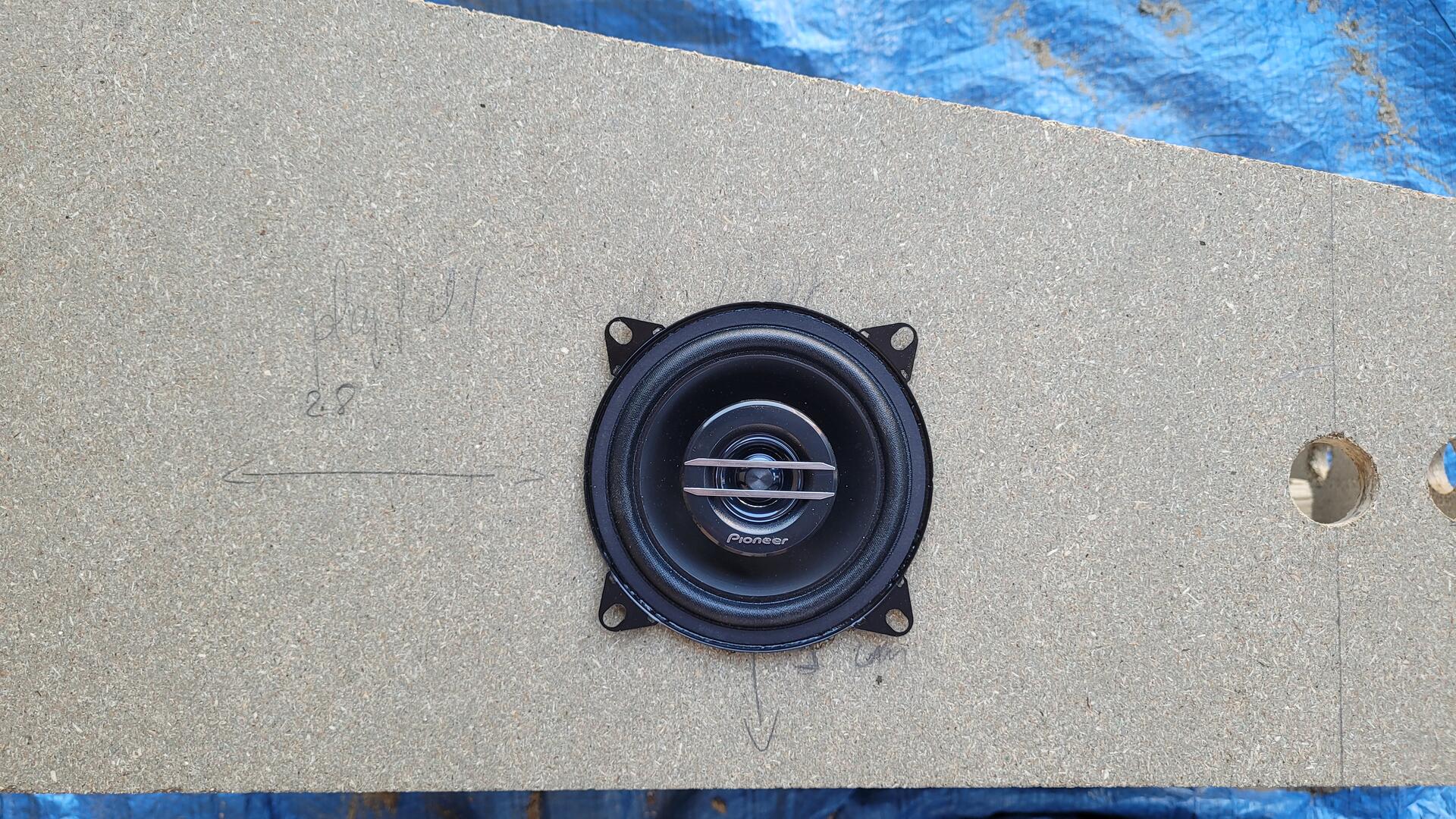
- A pair of 10 cm Pioneer car speakers (TS-G1020F)
- A 75mm sliding potentiomer (Fader) SC6080GH
- An 12V numerical audio amp (TDA7297), 2x15W
- 4 plastic washers to put the motherboard on (about 5mm high and with a diameter of 1.2cm)
Initial plans
Plan and dimensions
The initial plans I made are available for download here. This is a simple Libreoffice document.
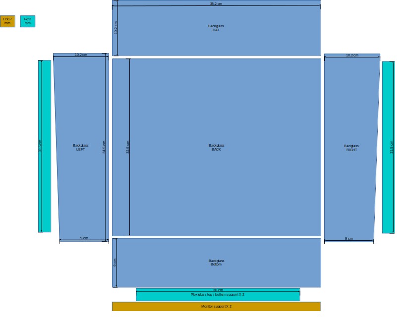
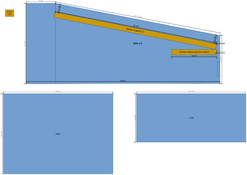
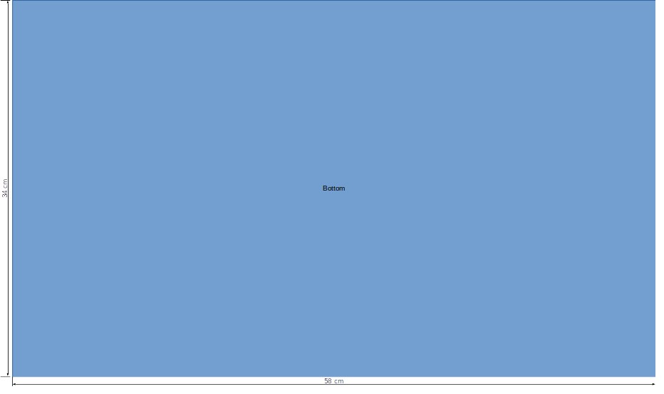
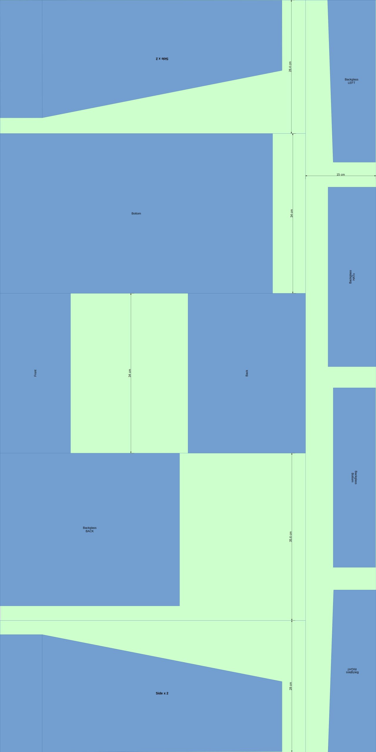
Wood cut plan
As I used a single board of 160x80cm, I planned the cut as following. The goal was to get clean border as much as possible for visible parts. Again, the file can be downloaded here.
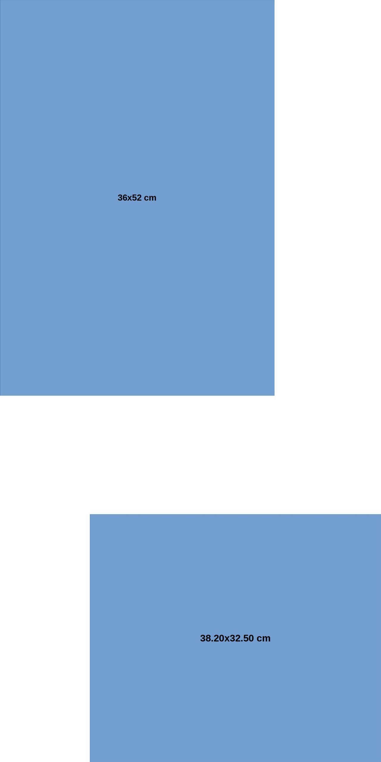
Plexiglass cut plan
I used some plexiglass to protect display pannels. I used a 100x50cm board, so below is how I cut needed pieces :
The Build
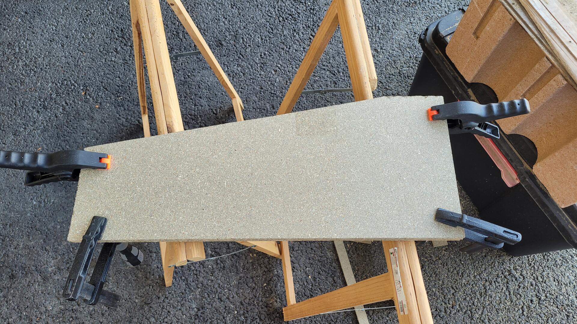
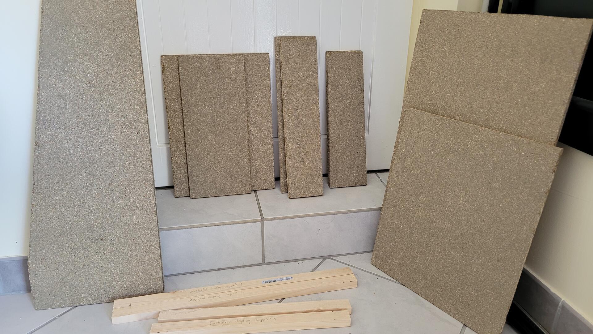
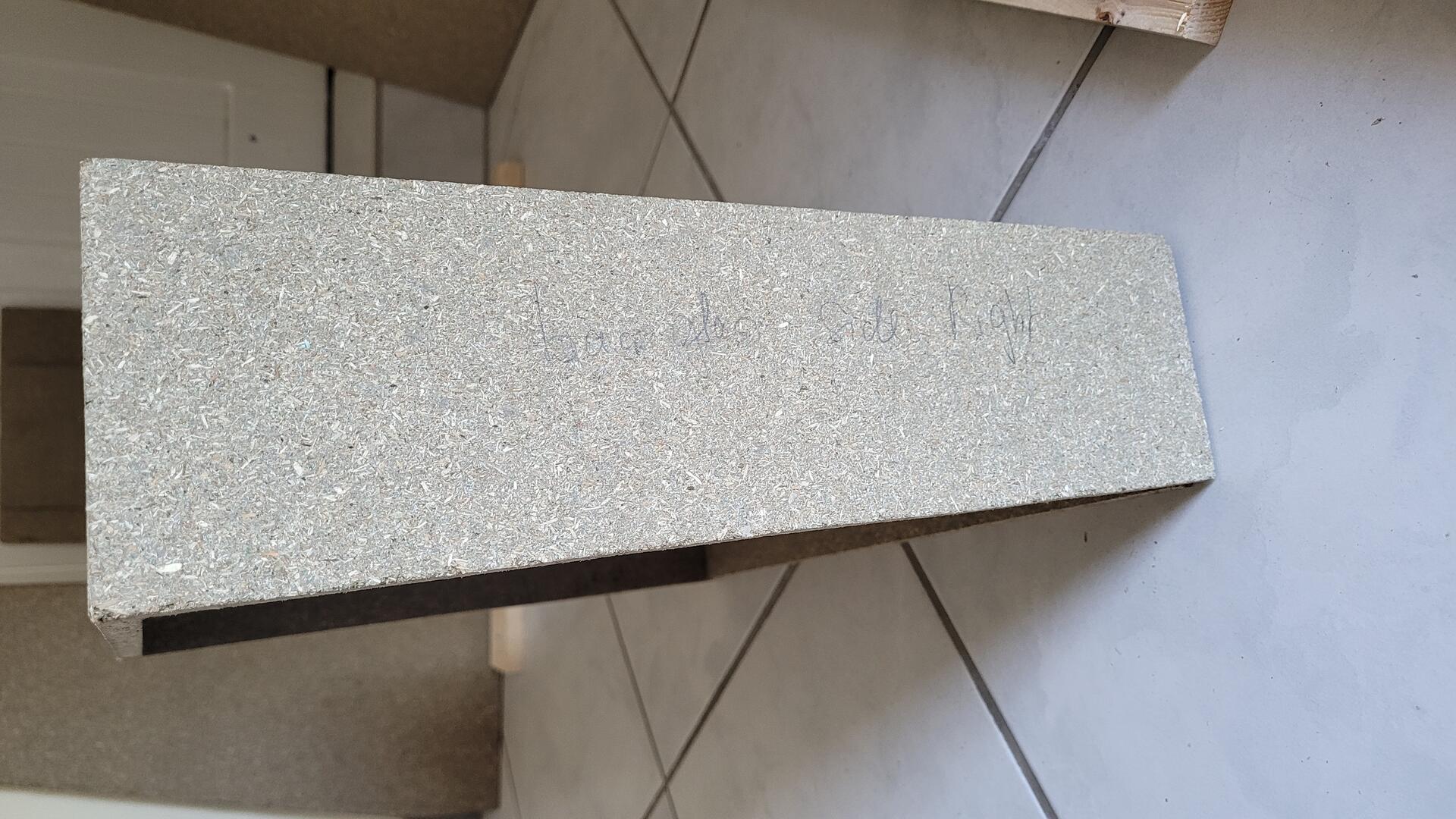
Wood cut
To cut all parts, I used both a circular saw and a jig saw. As you can see on the first photo, for the parts that had to be identical, I filed them together. On the right, all pieces of wood, ready to be assembled 🙂
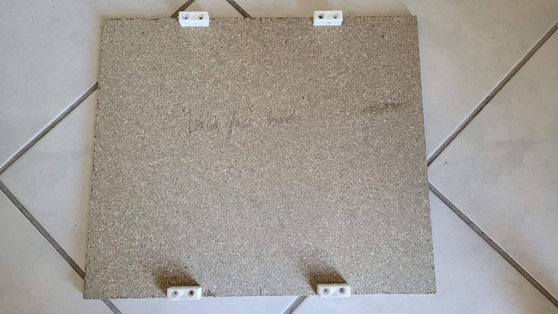
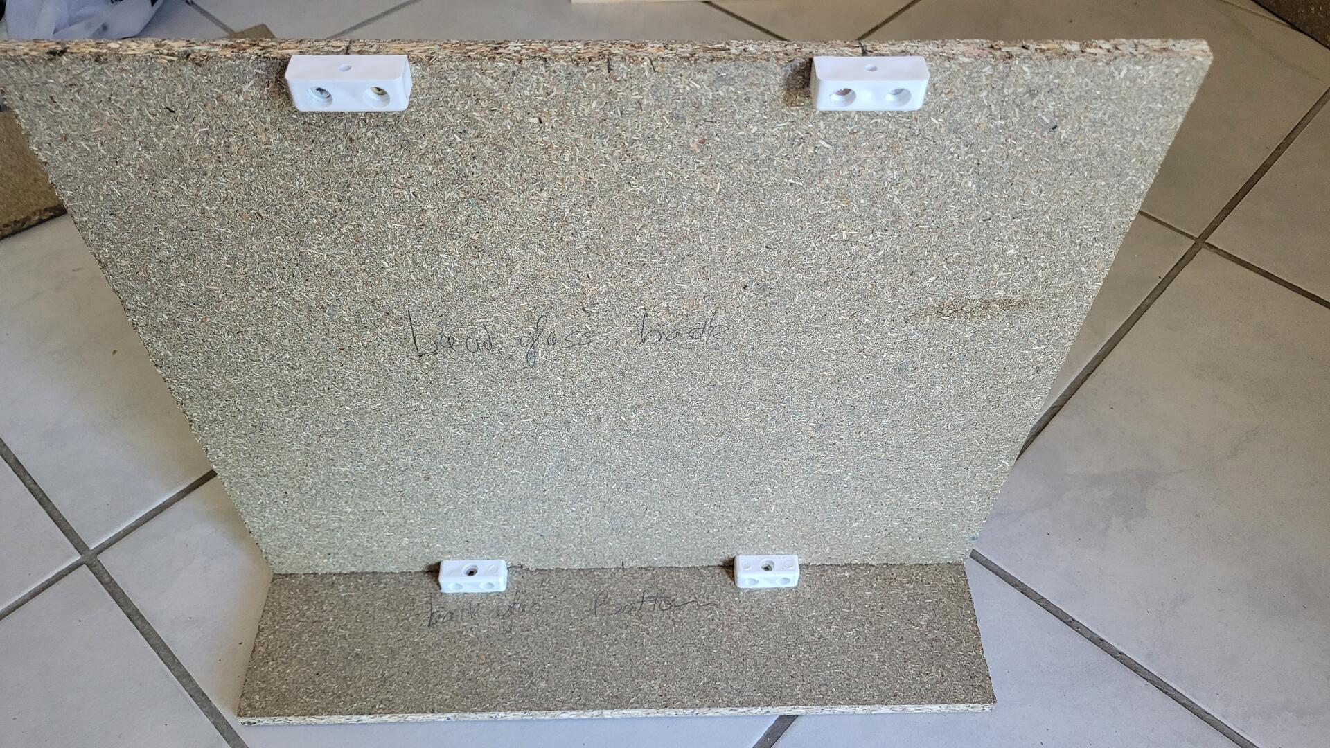
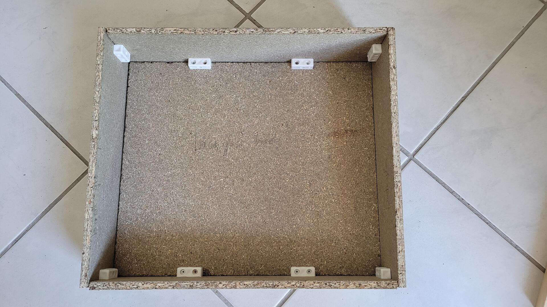
Backglass structure
All the parts are assembled using plastic brackets. The wood is far too thin to skew on the side. Here is the assembly of the bacckglass structure.
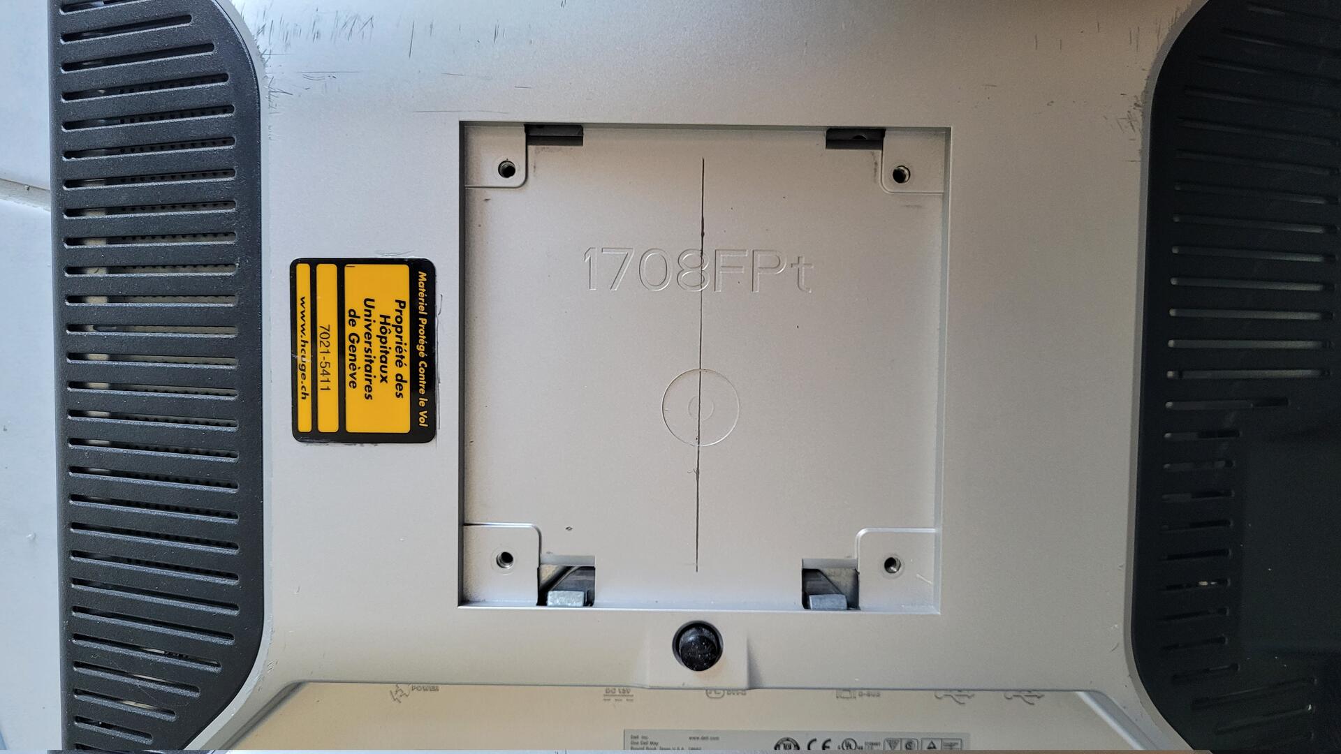
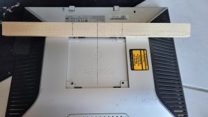
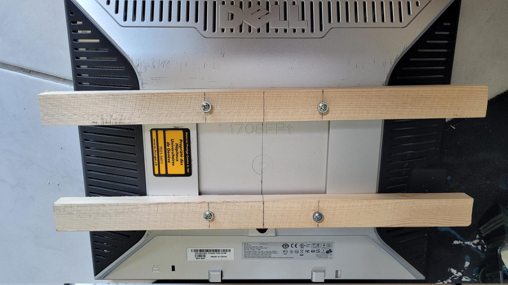
In order to fix the display inside the backglass, I used two pine wood cleats and screwed them through the VESA holes. Due to an error, the wood cleats are not perfectly straight, but when all is fixed, the screen is well aligned, which is what is the most important at the end.
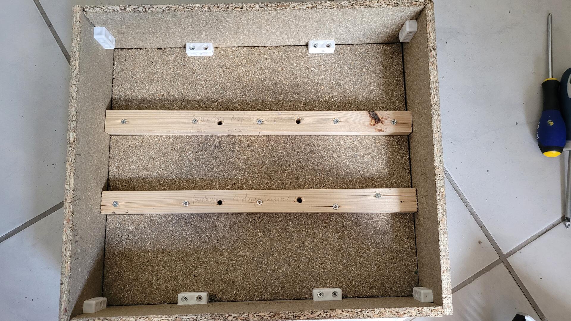
Finaly, I did one hole on the bottom part of the case to pass power and DVI cables, and several small holes on the back to get some air flow to keep the display cool.
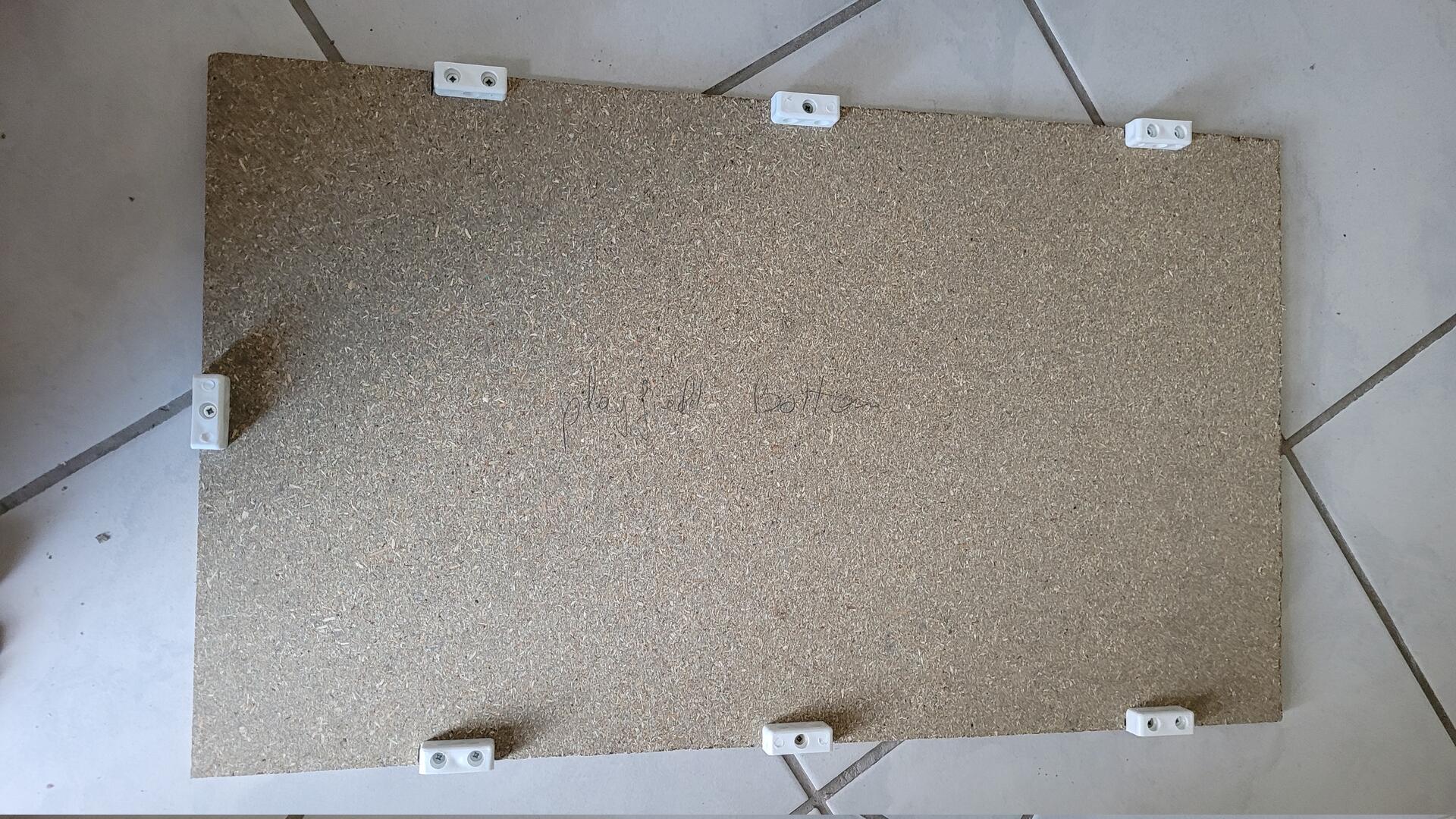
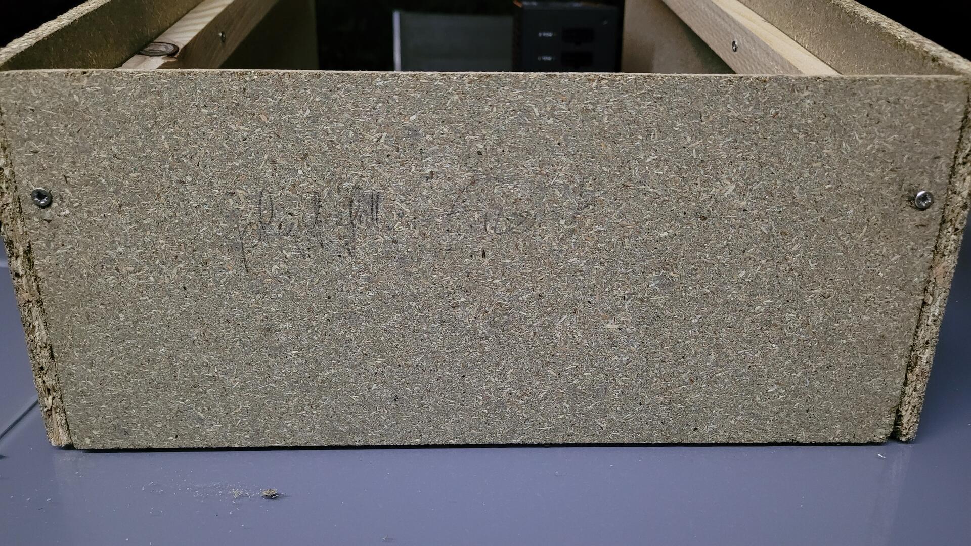
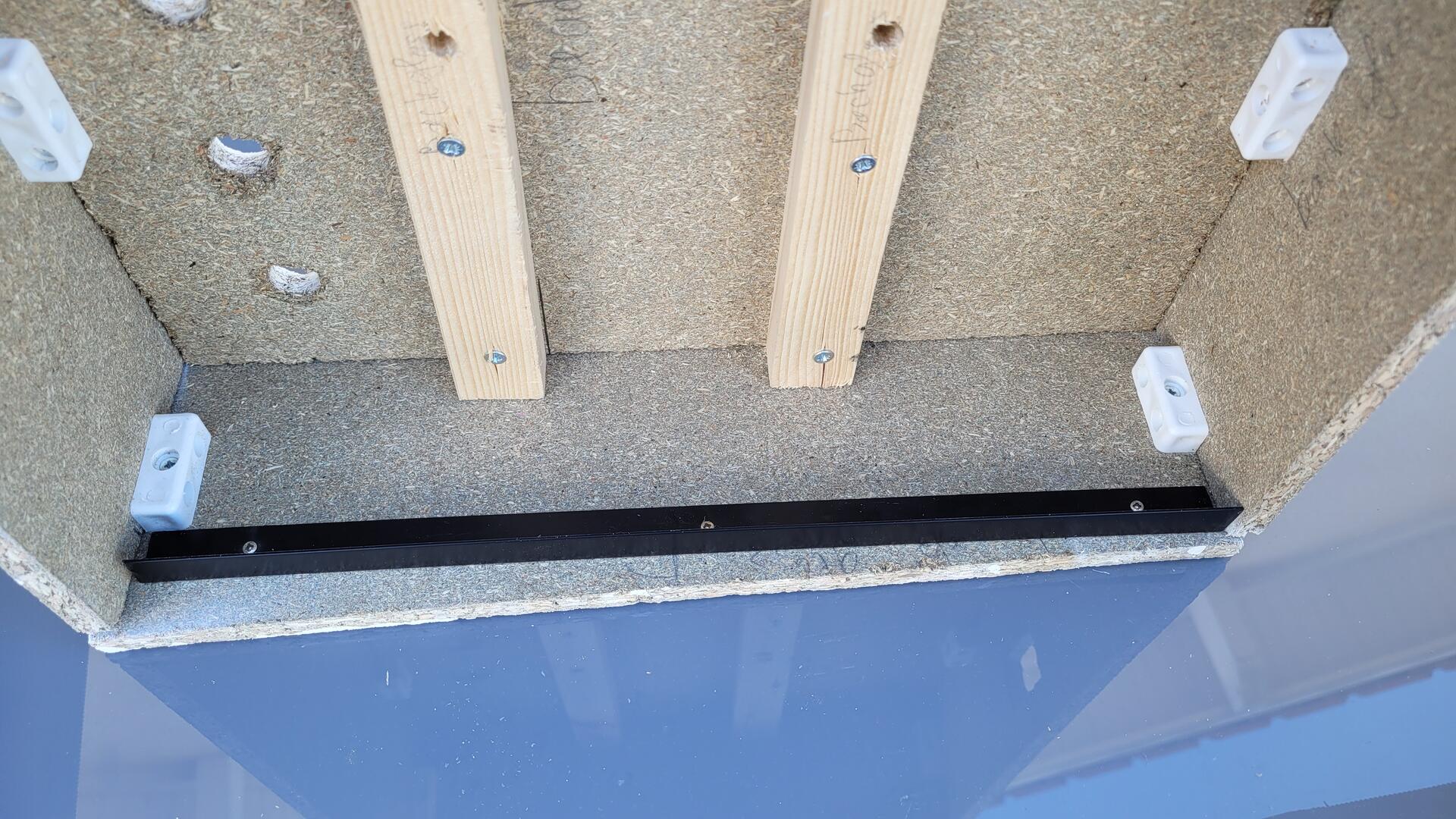
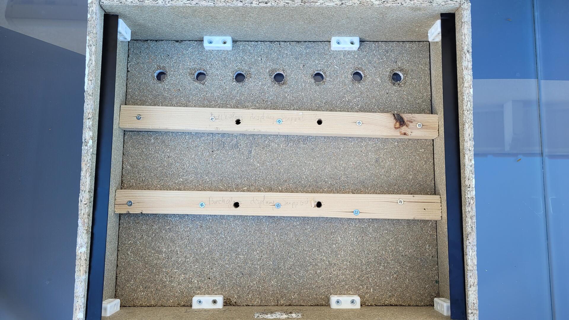
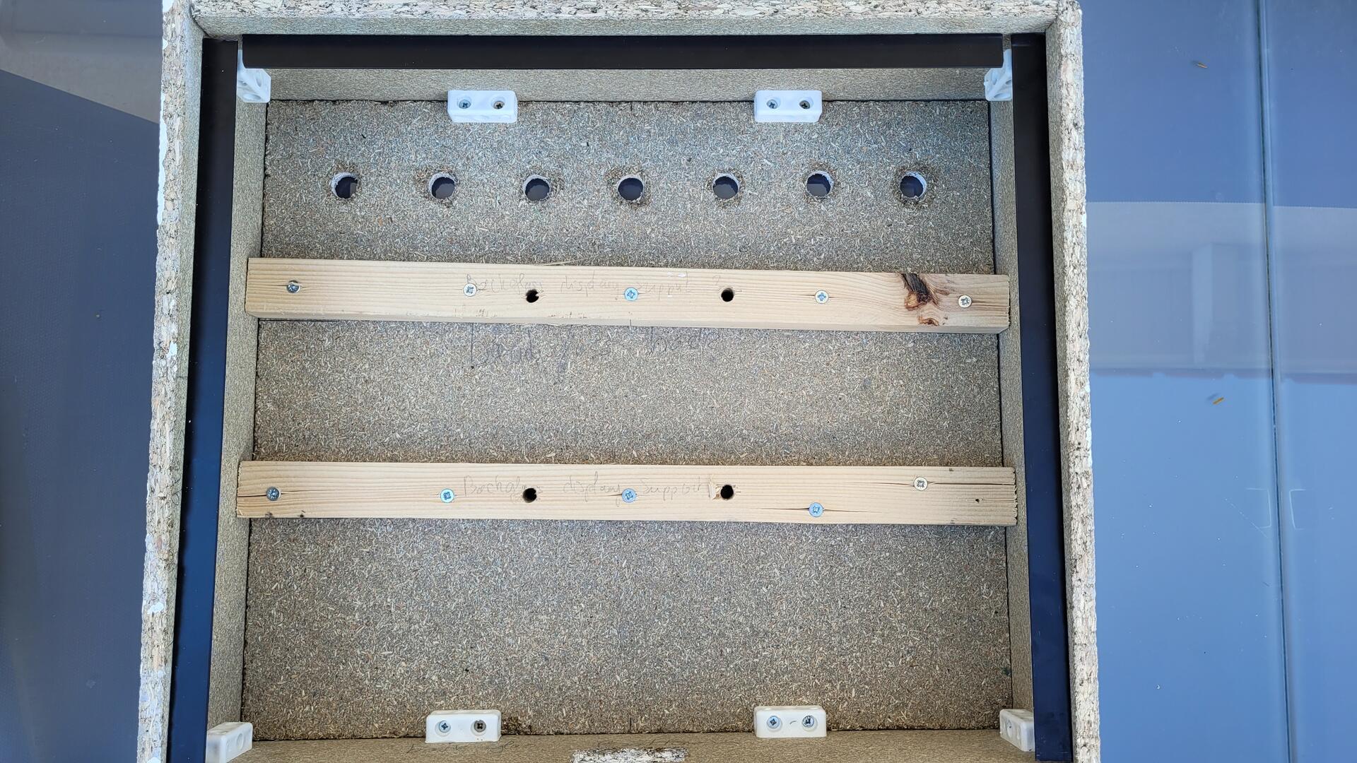
Playfield structure
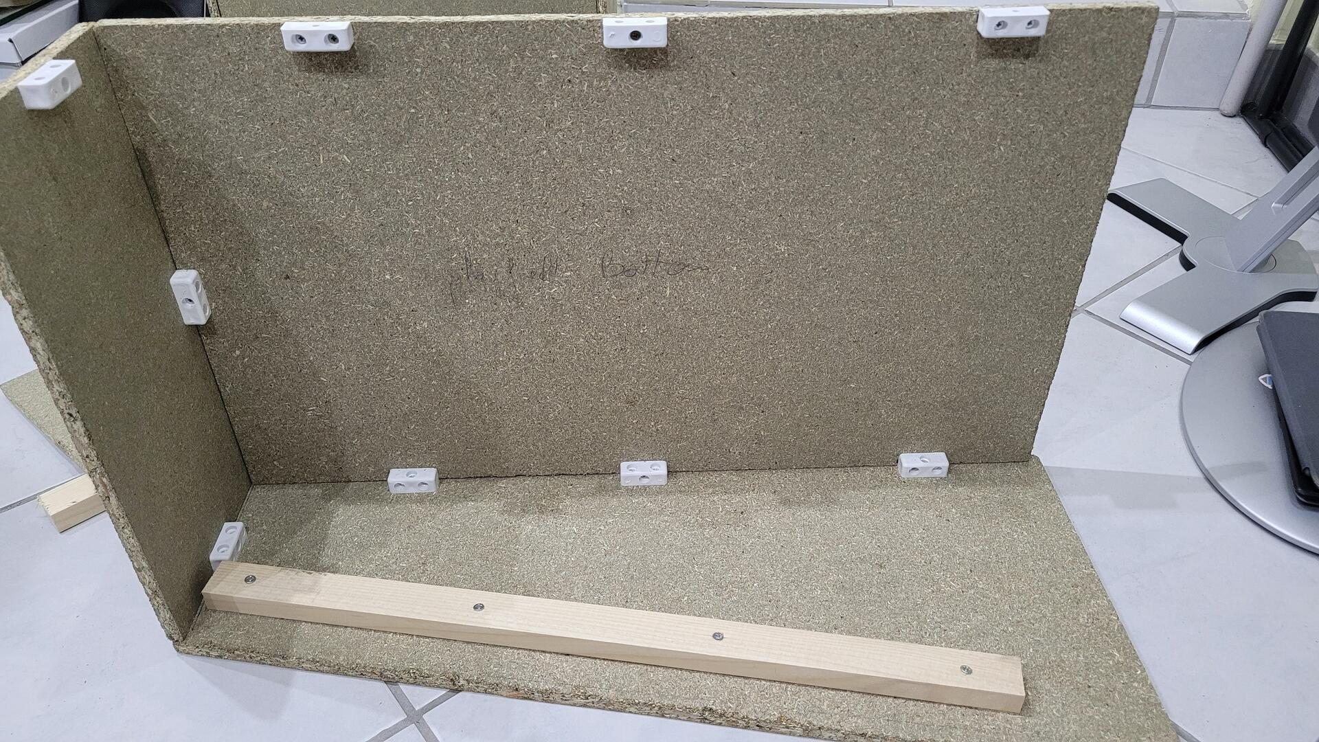
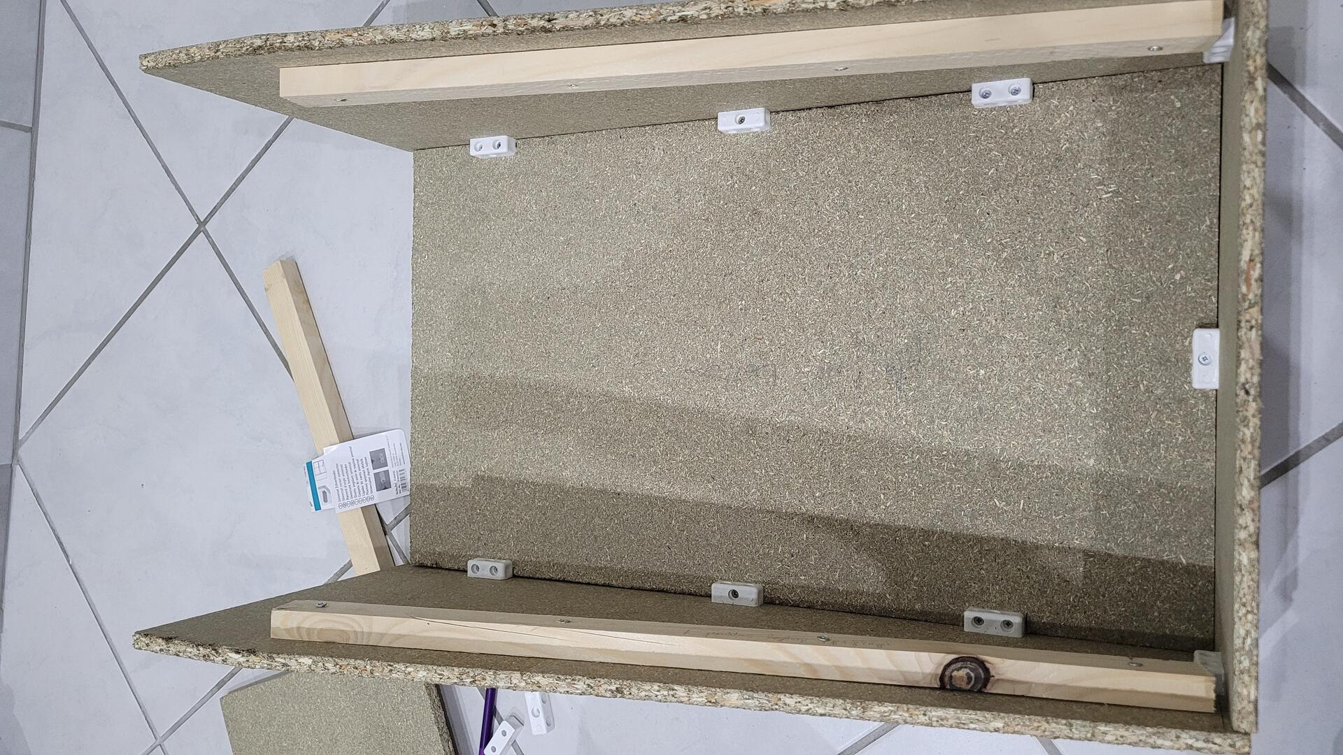
The play field structure is assembled the same way as the backglass. However, here the wood cleats used on both side serve as a bed for the screen. The width of the cabinet is tight enough to let the screen fit with a little bit of force to be inserted. This ensure that the screen won’t move.
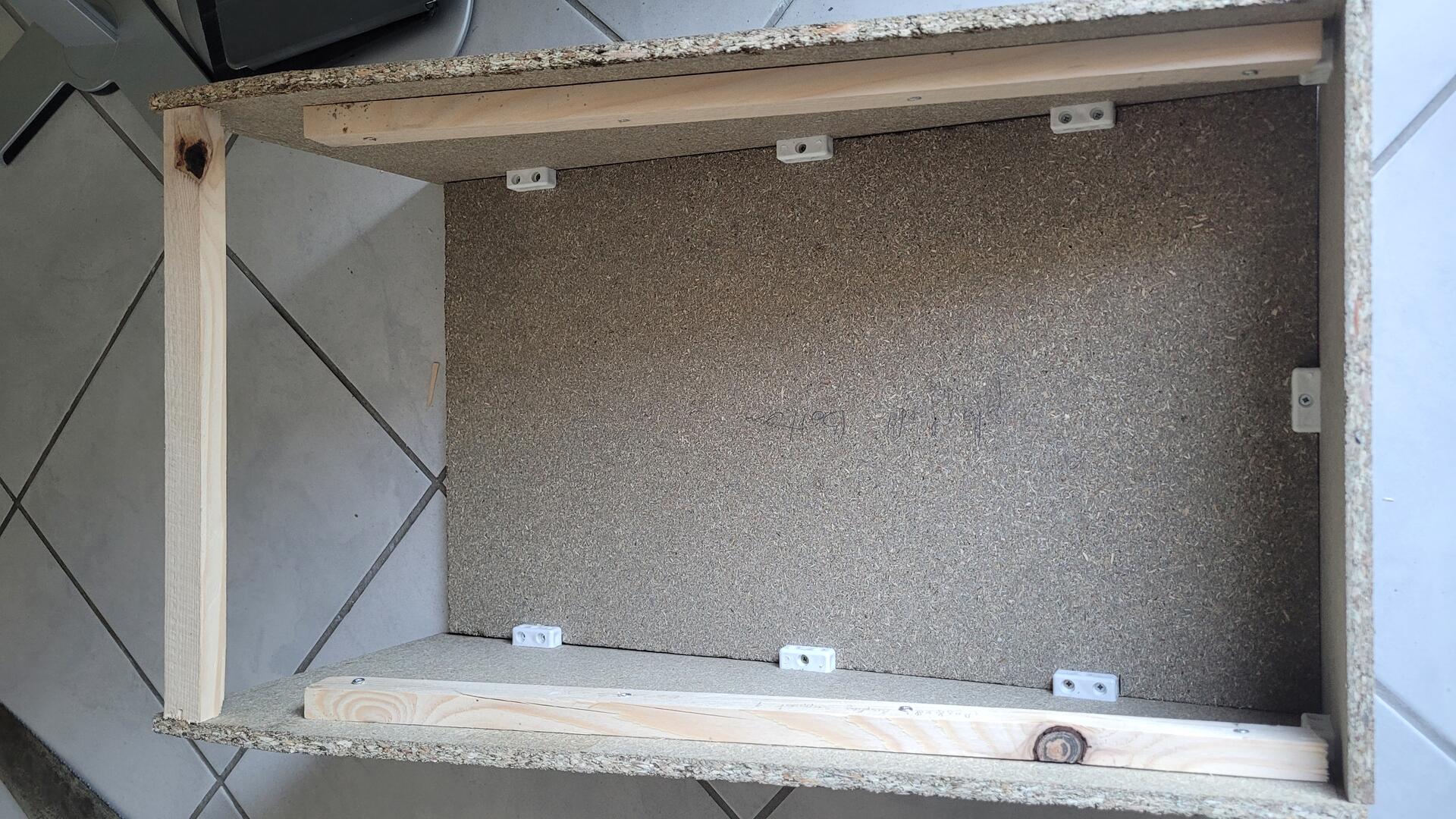
I also used a wood cleat on the back of the cabinet. Its purpose is to rigidify it, but also to screw the backglass structure on it later.
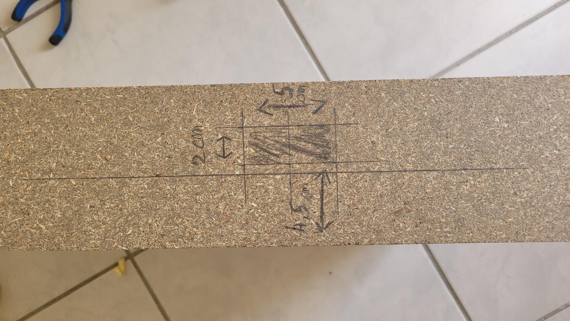
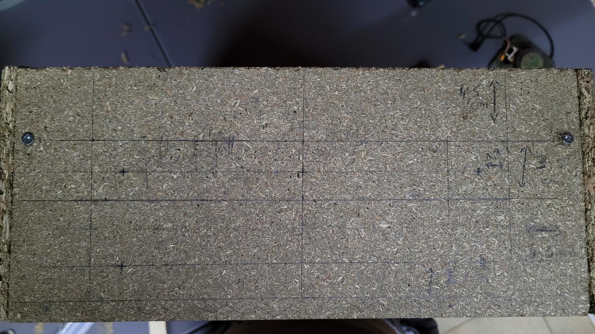
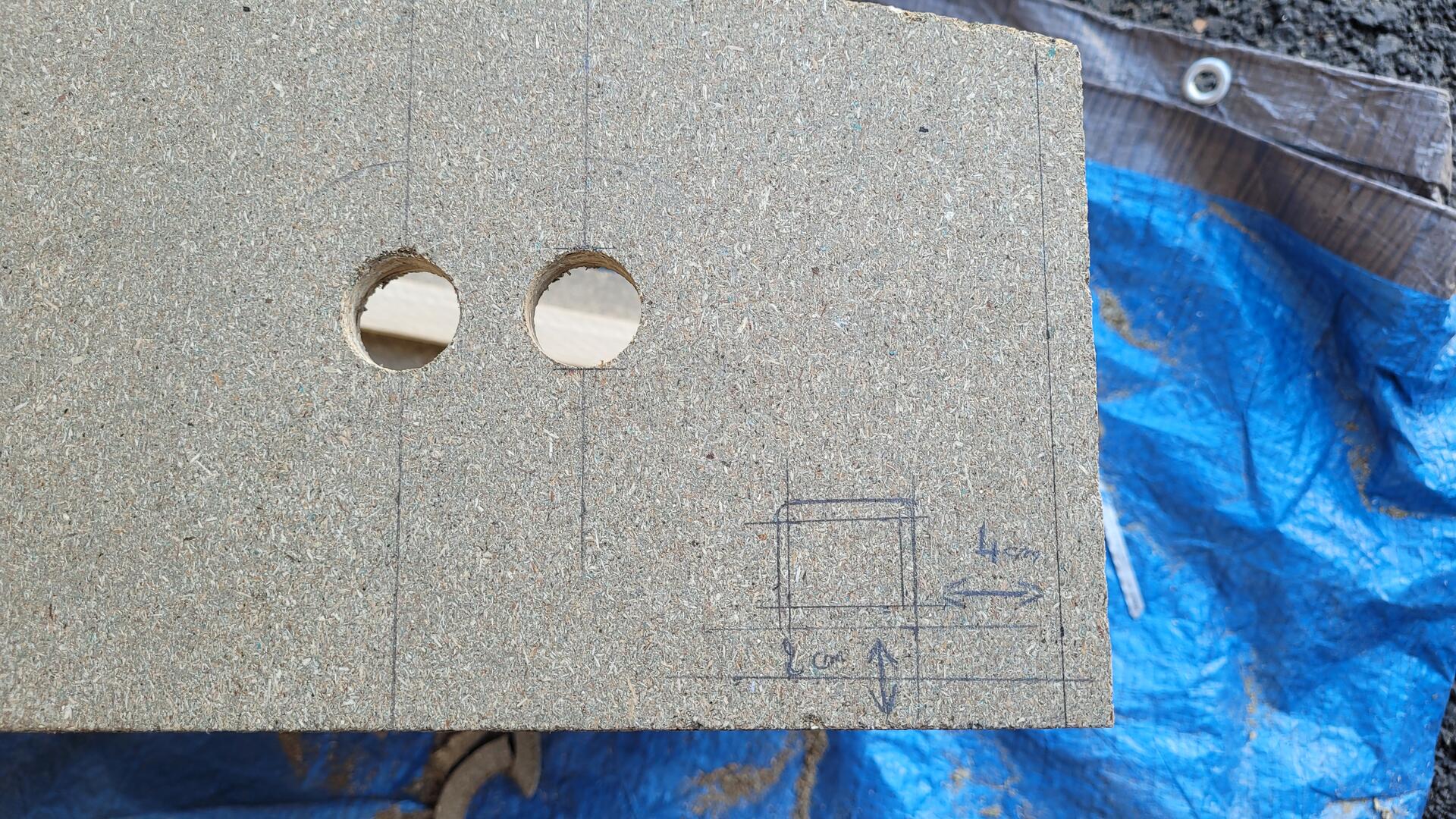
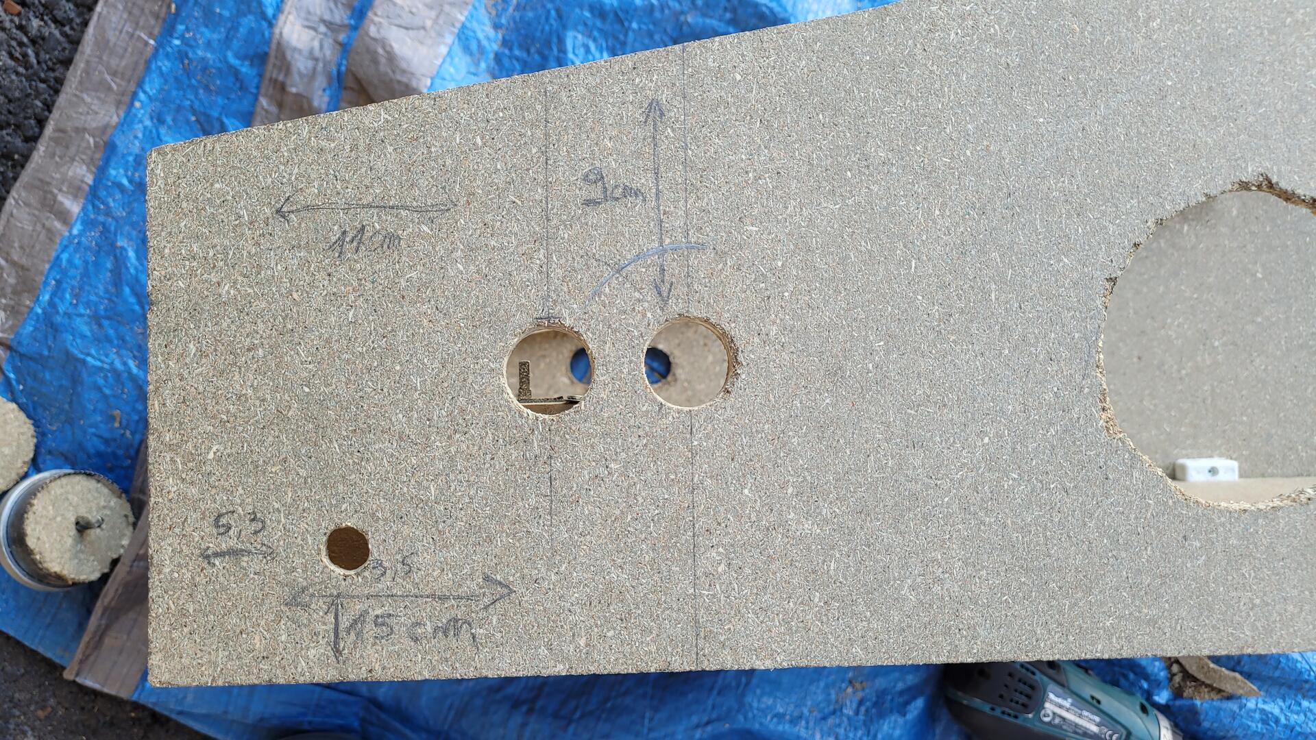
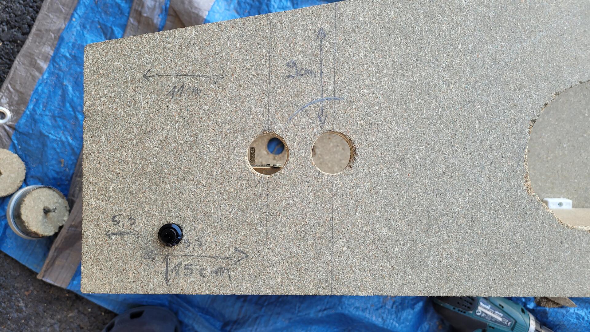
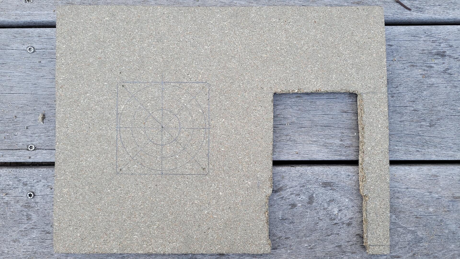
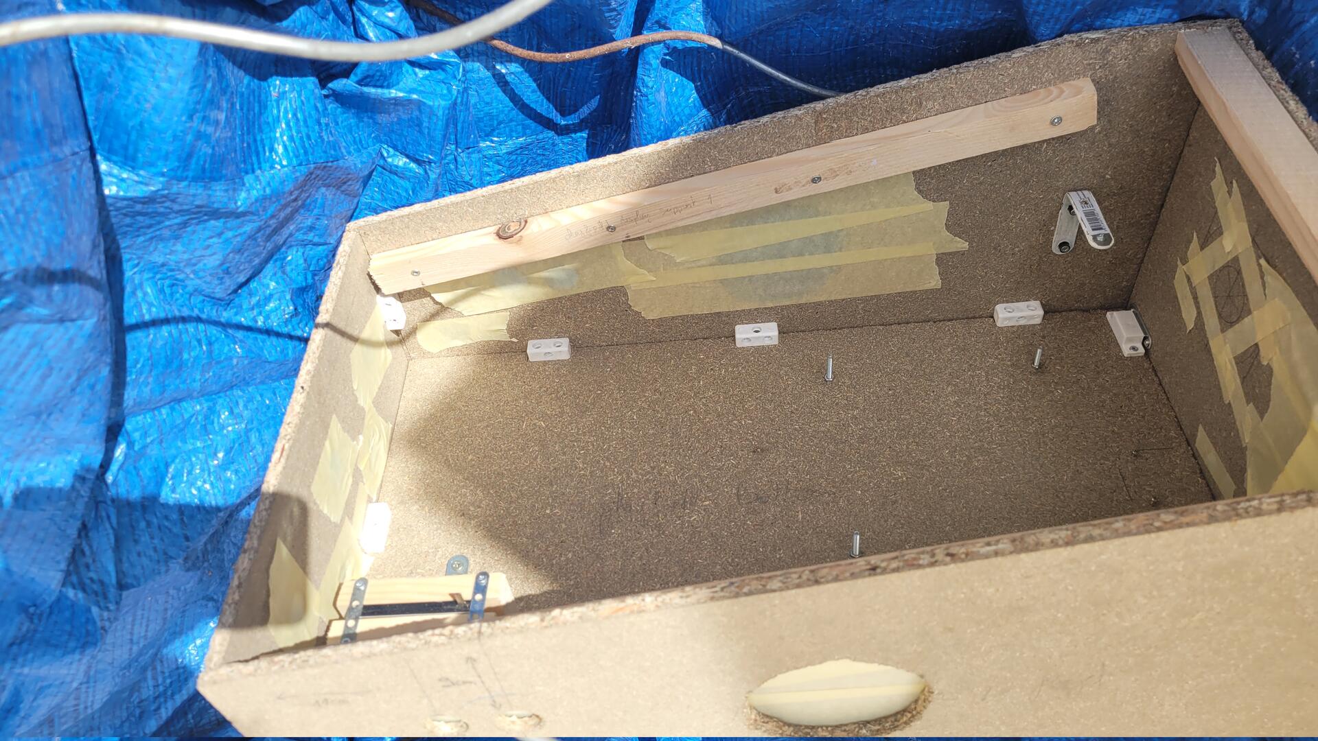
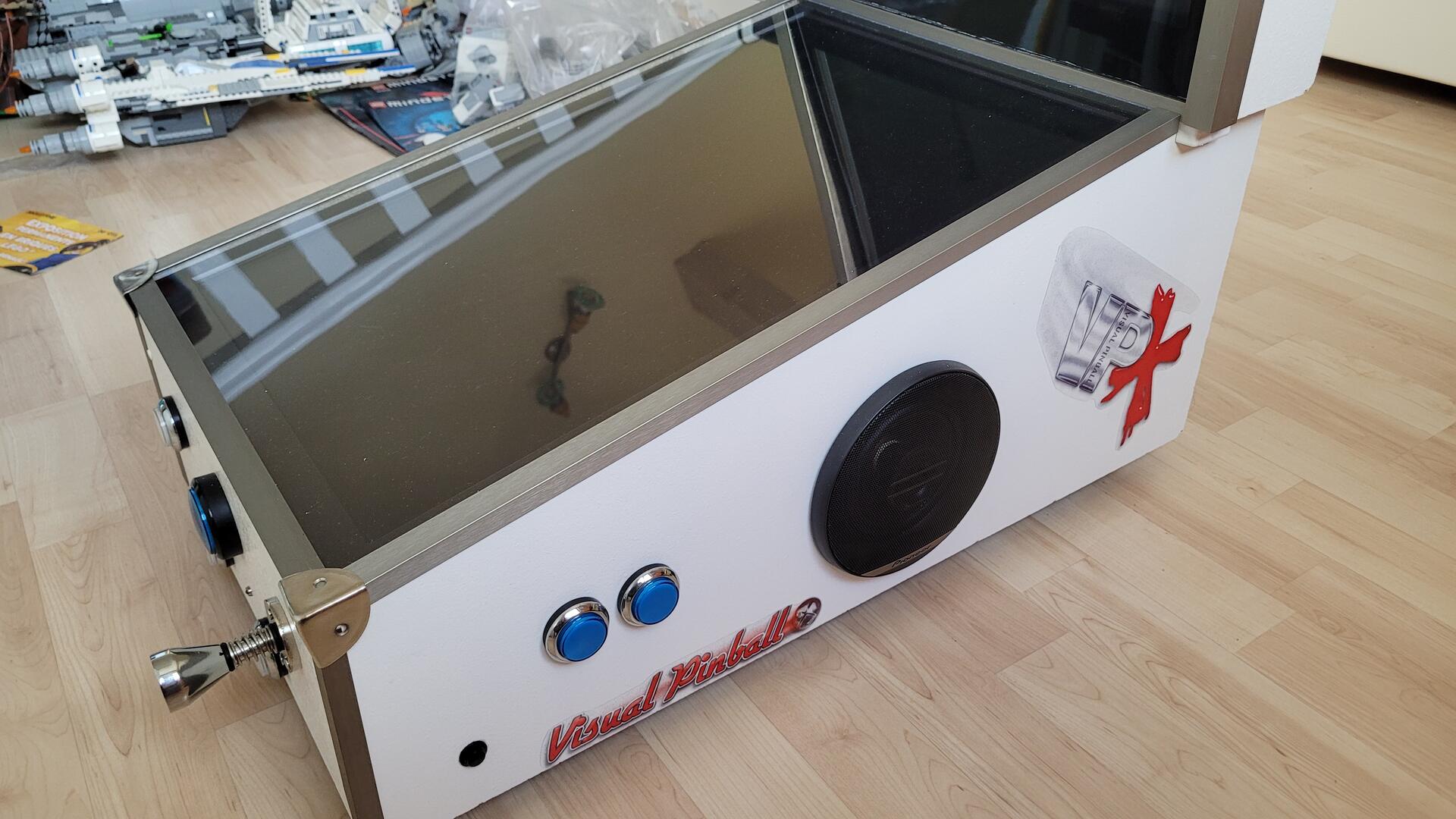
Playfield holes
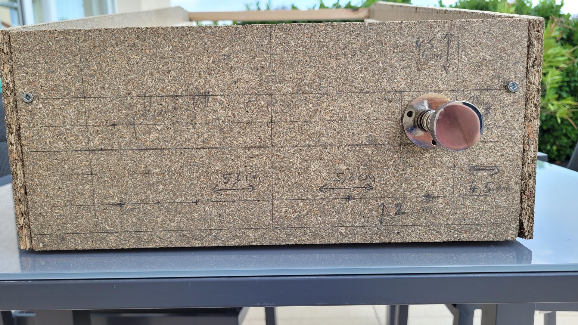
The playfield strucure being ready, the next step was to drill all the required holes before painting. I found it easier to make these holes on the mounted structure to better juge and appreciate their placement.
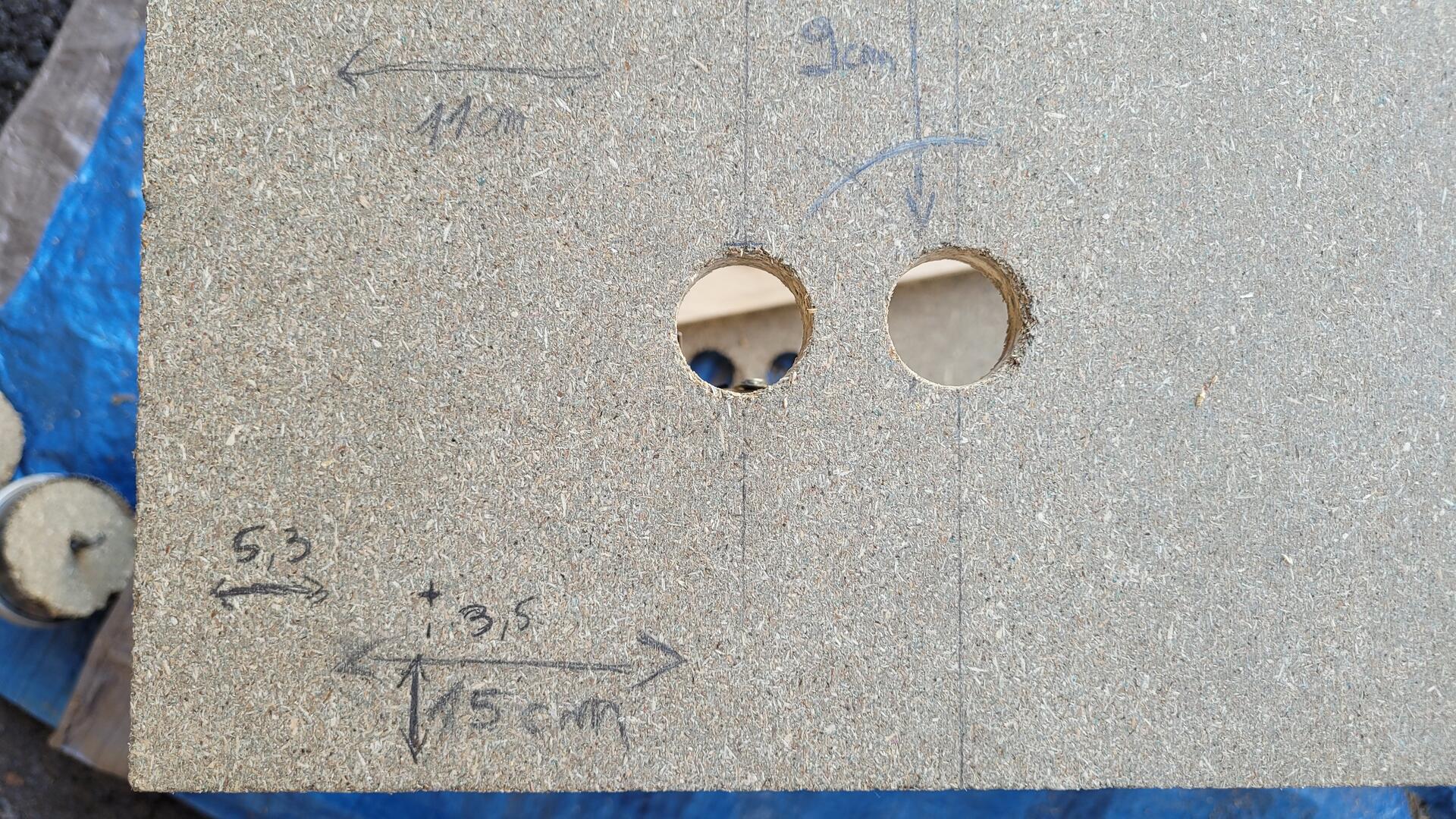
I noted all the dimensions I used directly on the wood. They should be easily viewable by clicking on any photo. Excepted for the speakers, I made the holes with a driller.
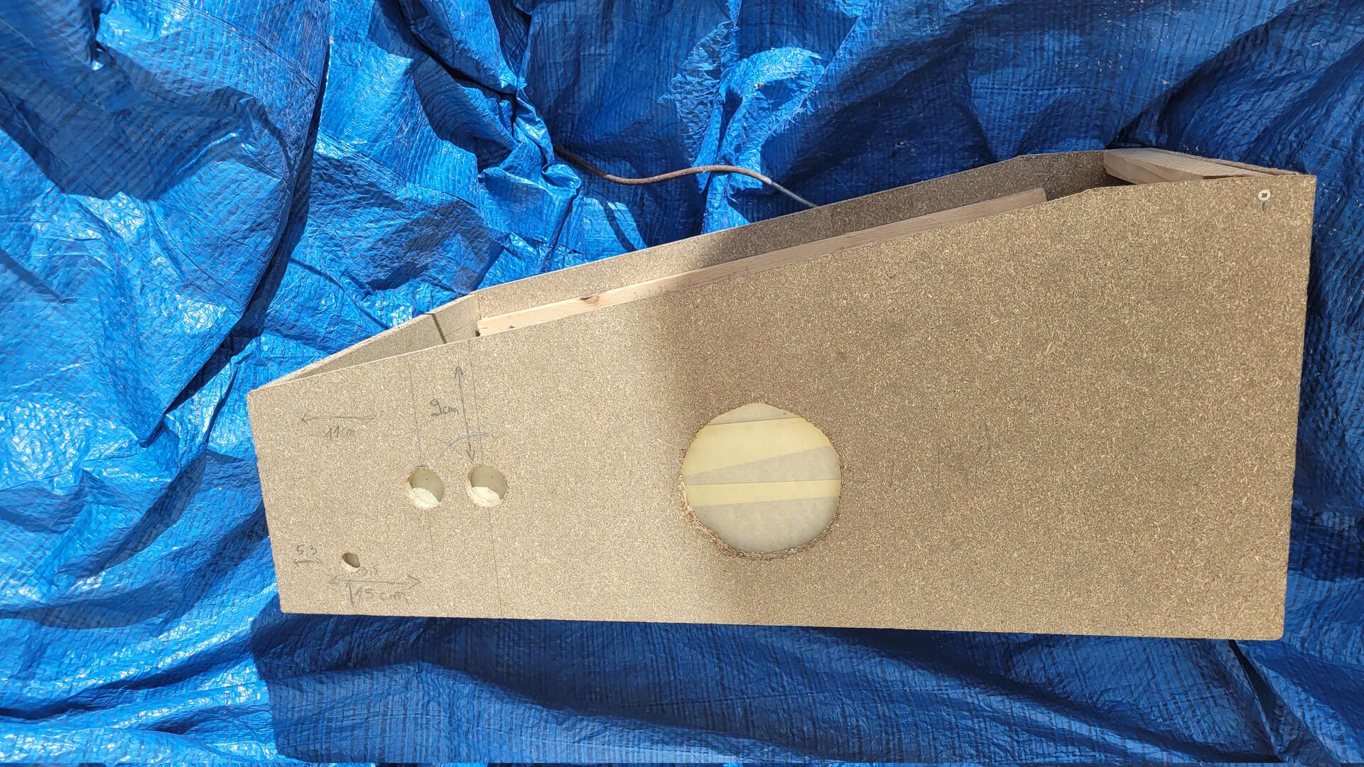
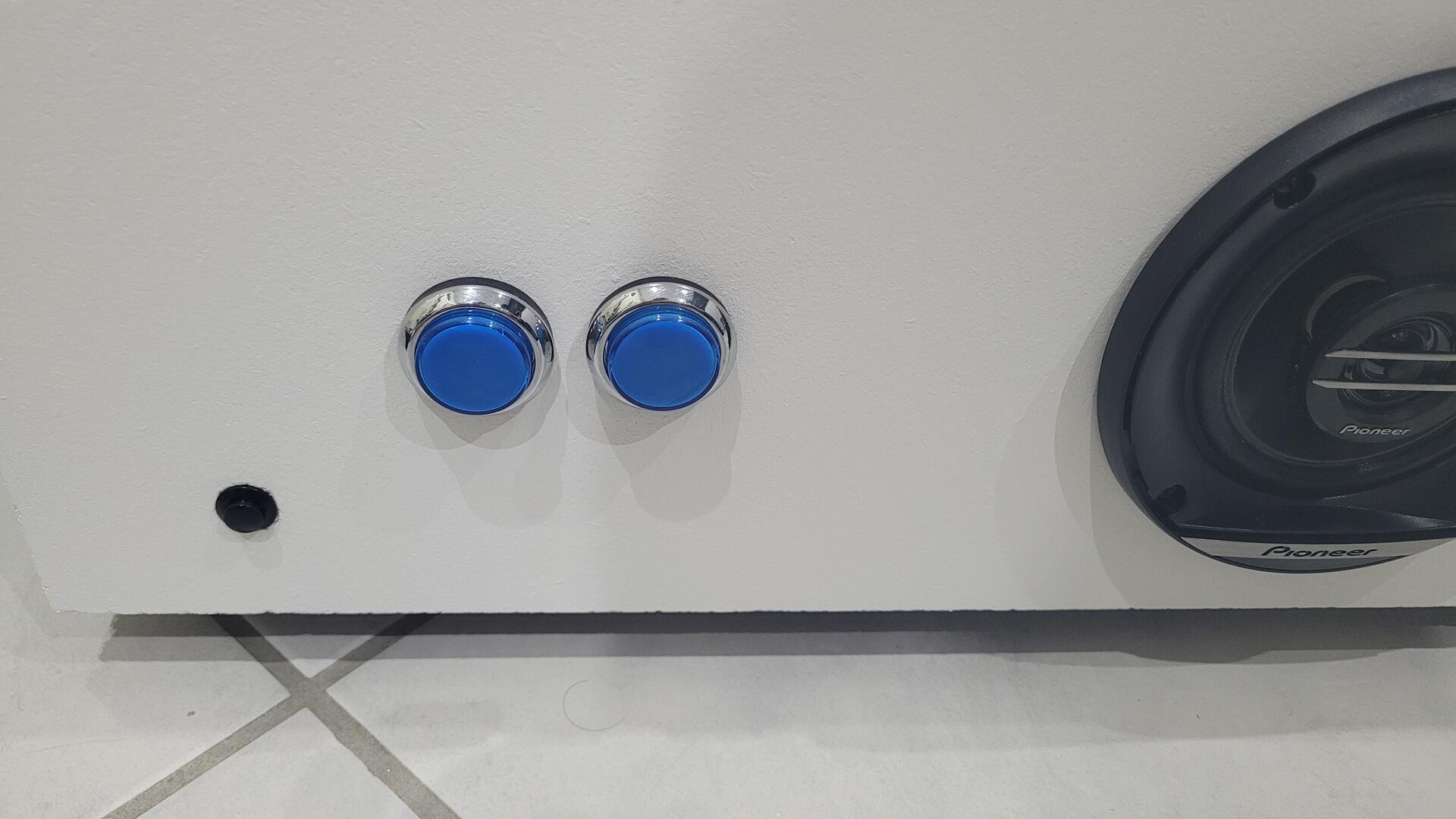
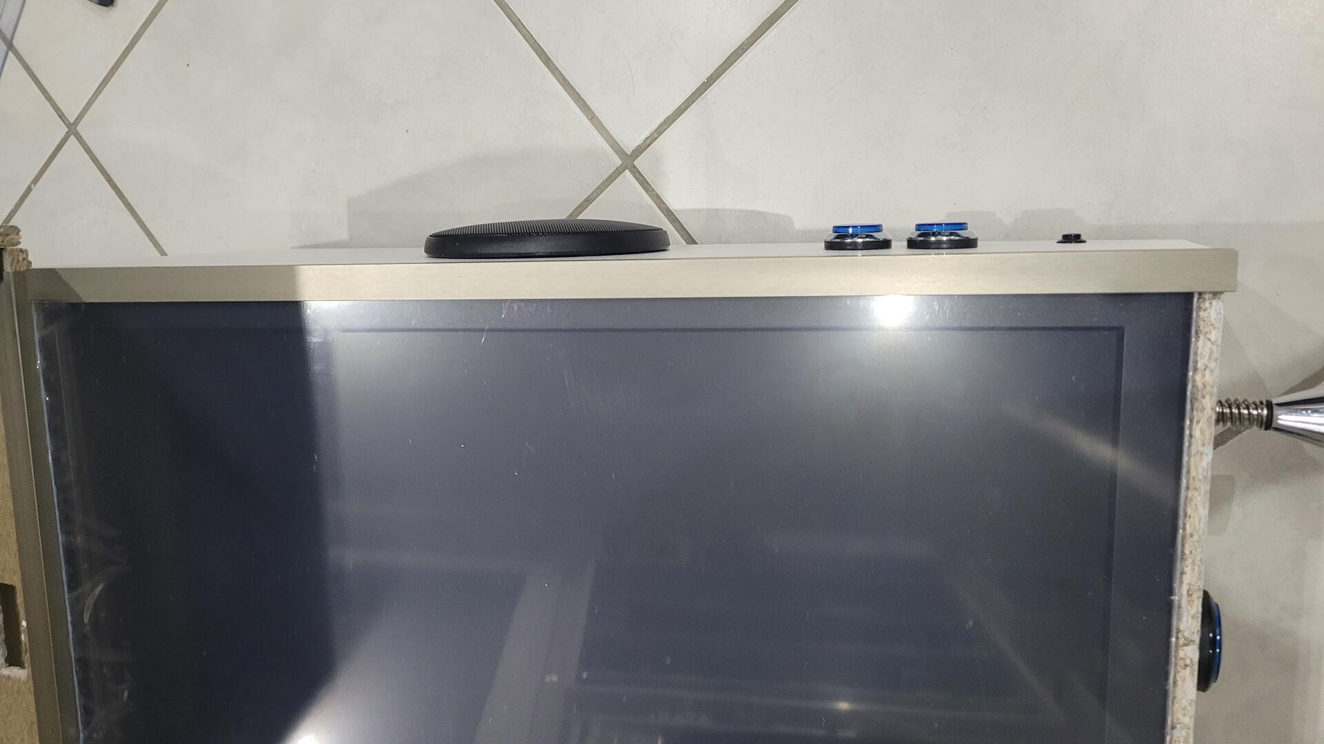
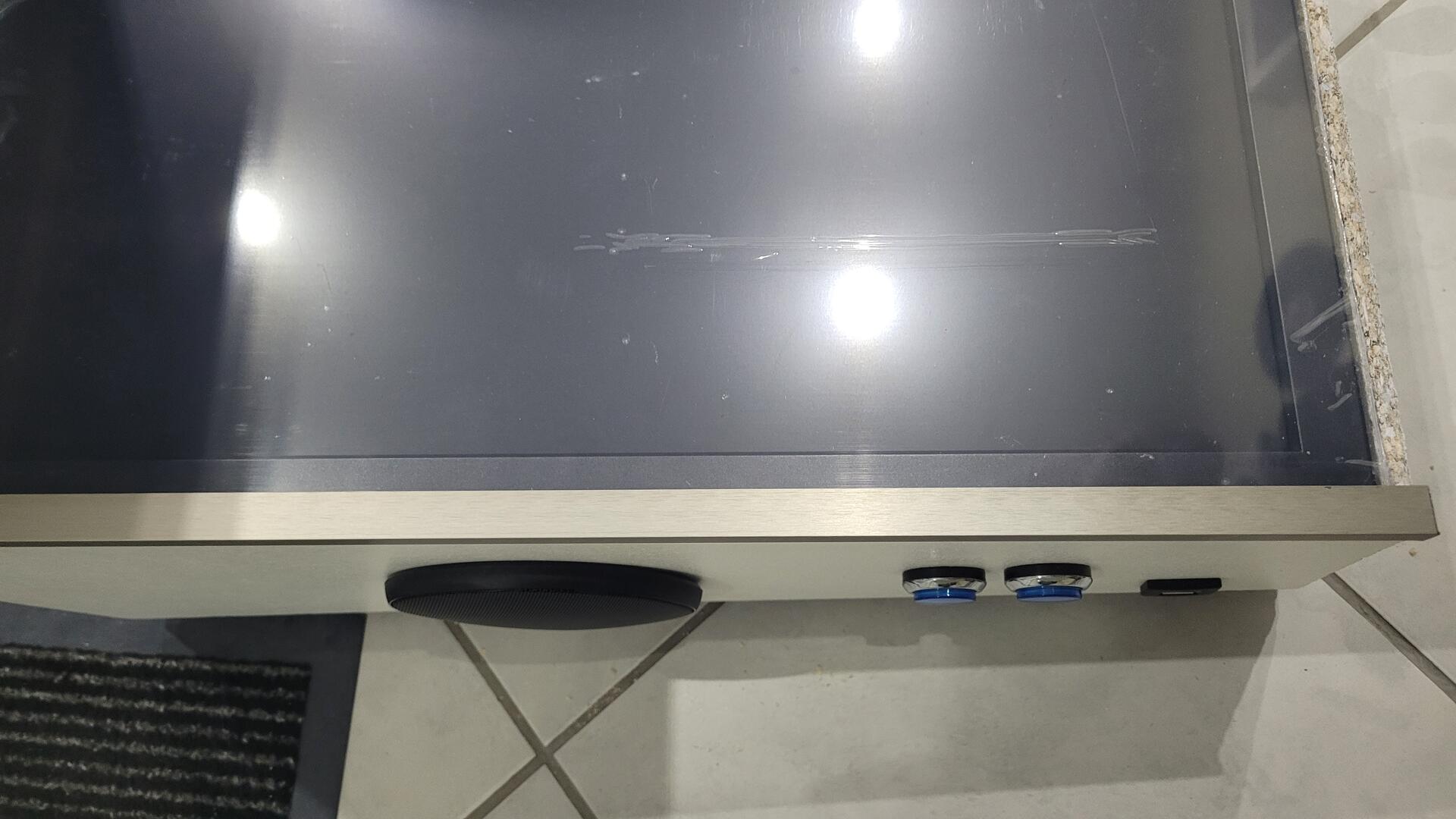
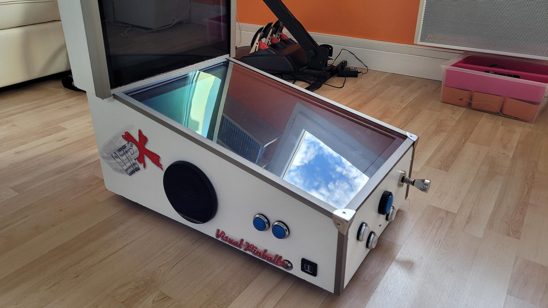
On each side : left / right flipper and left / right magna save buttons
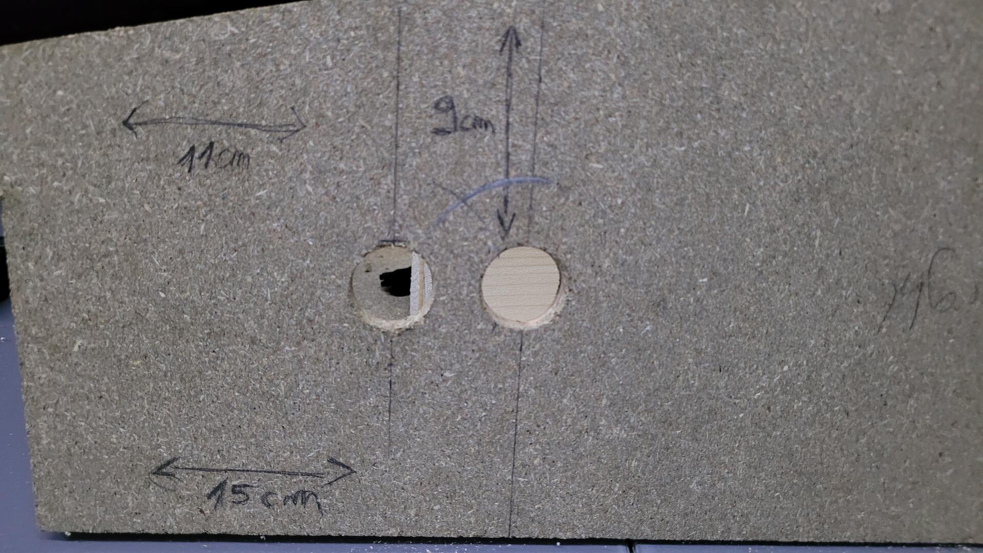
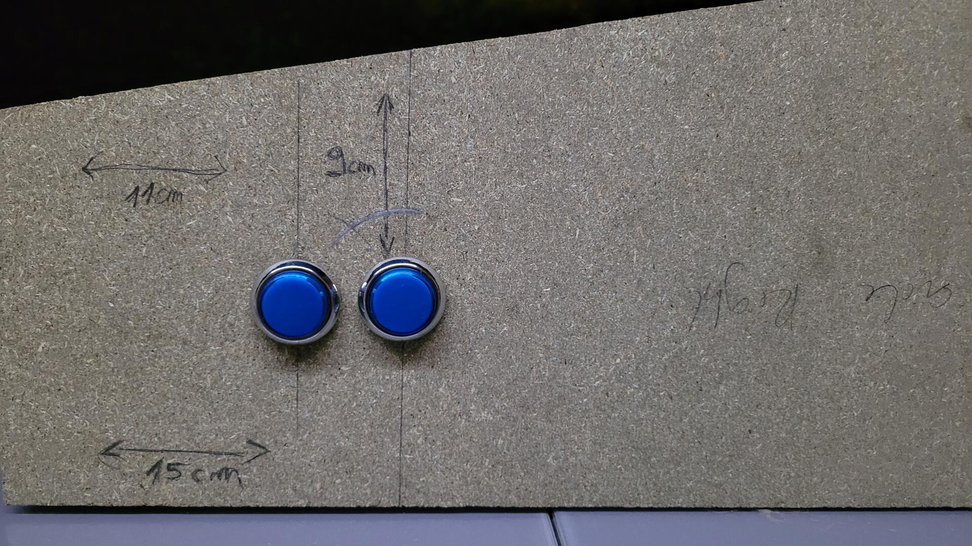
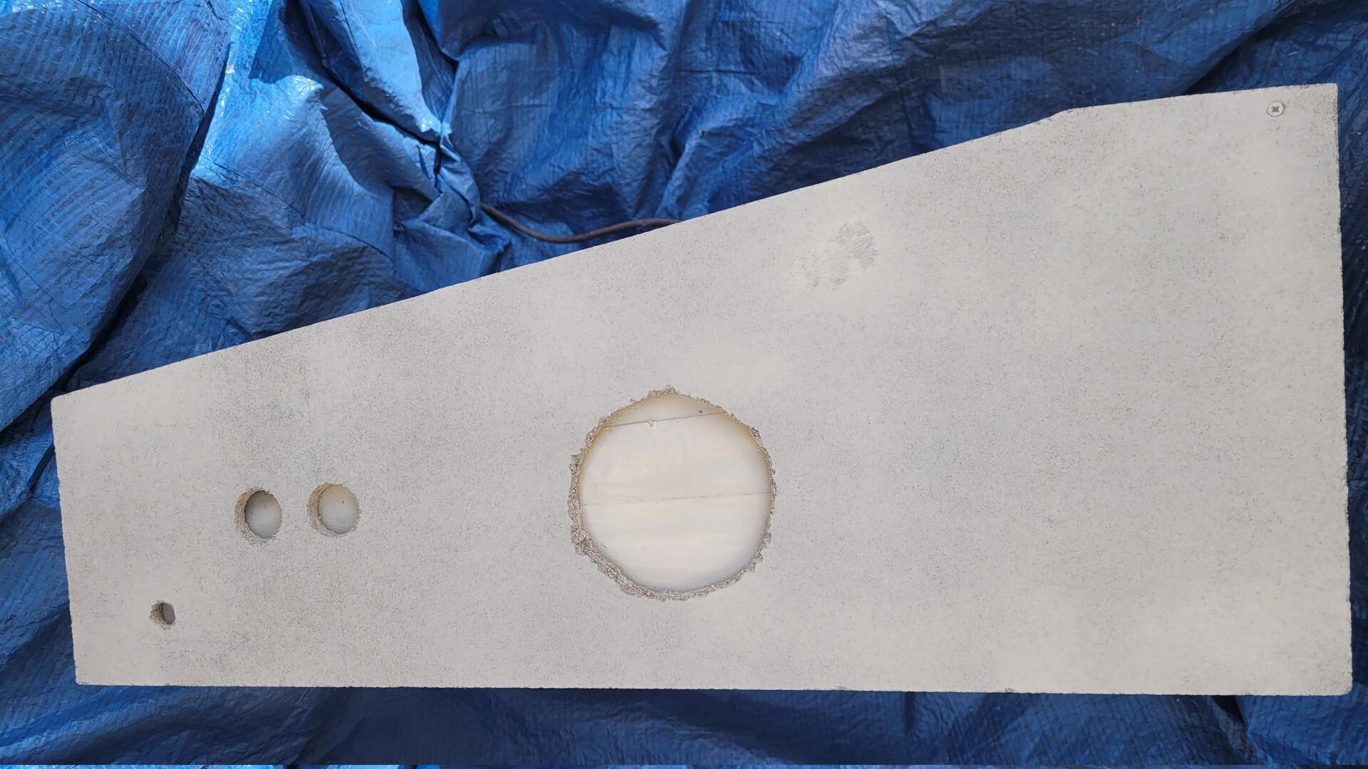
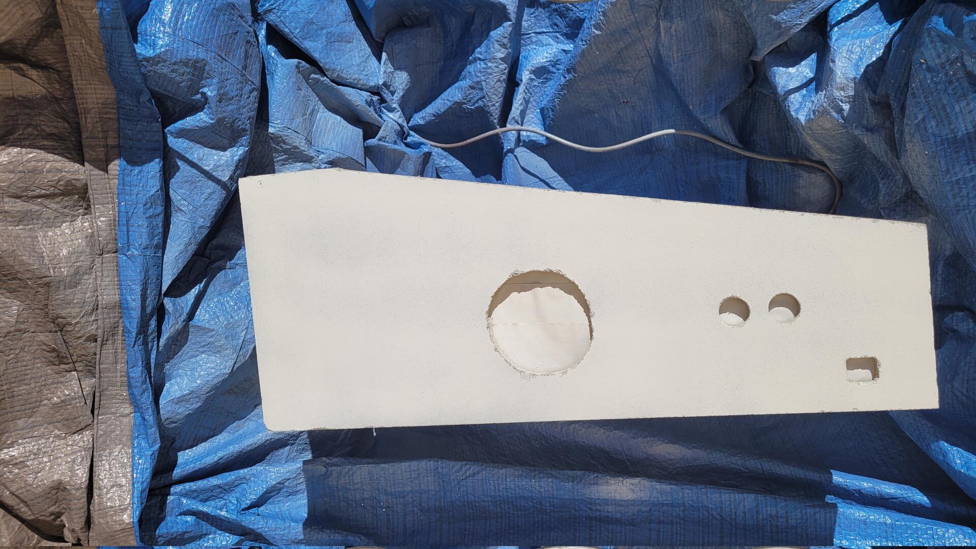
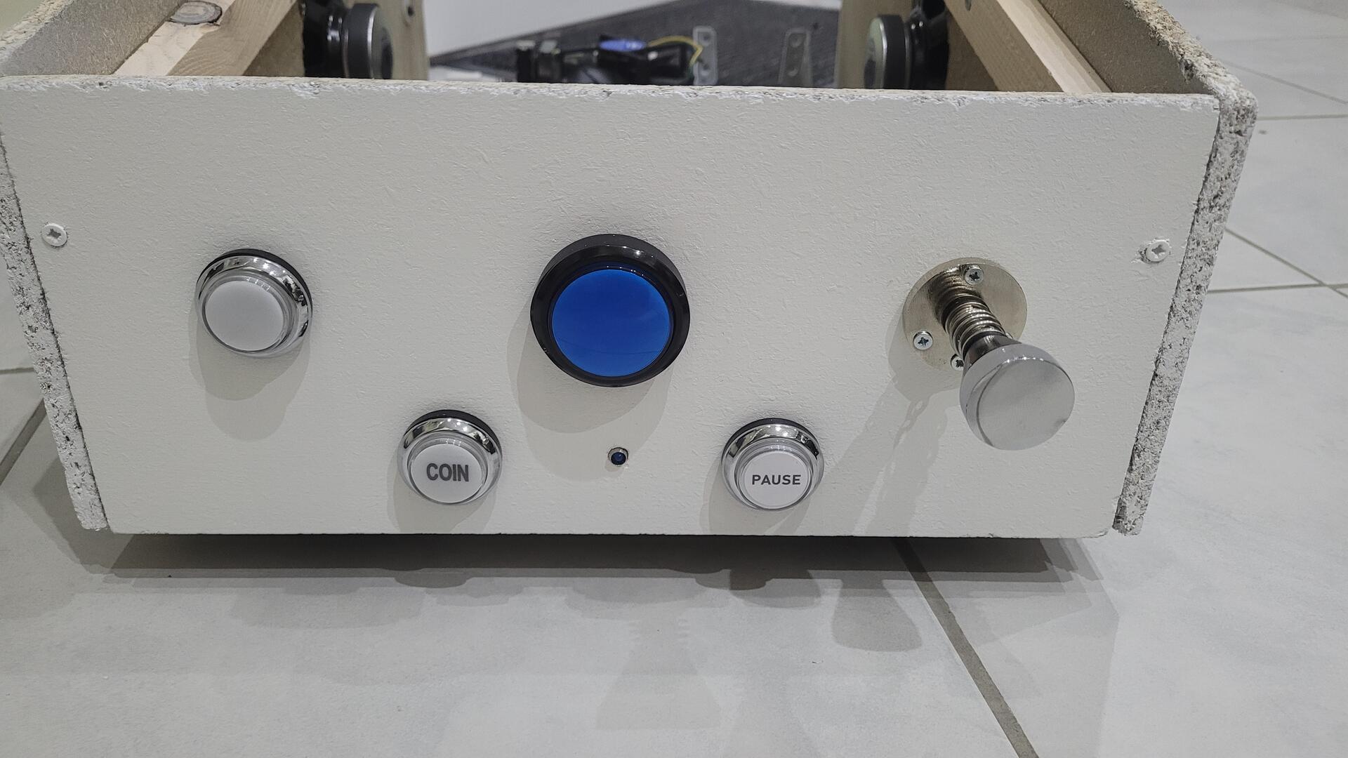
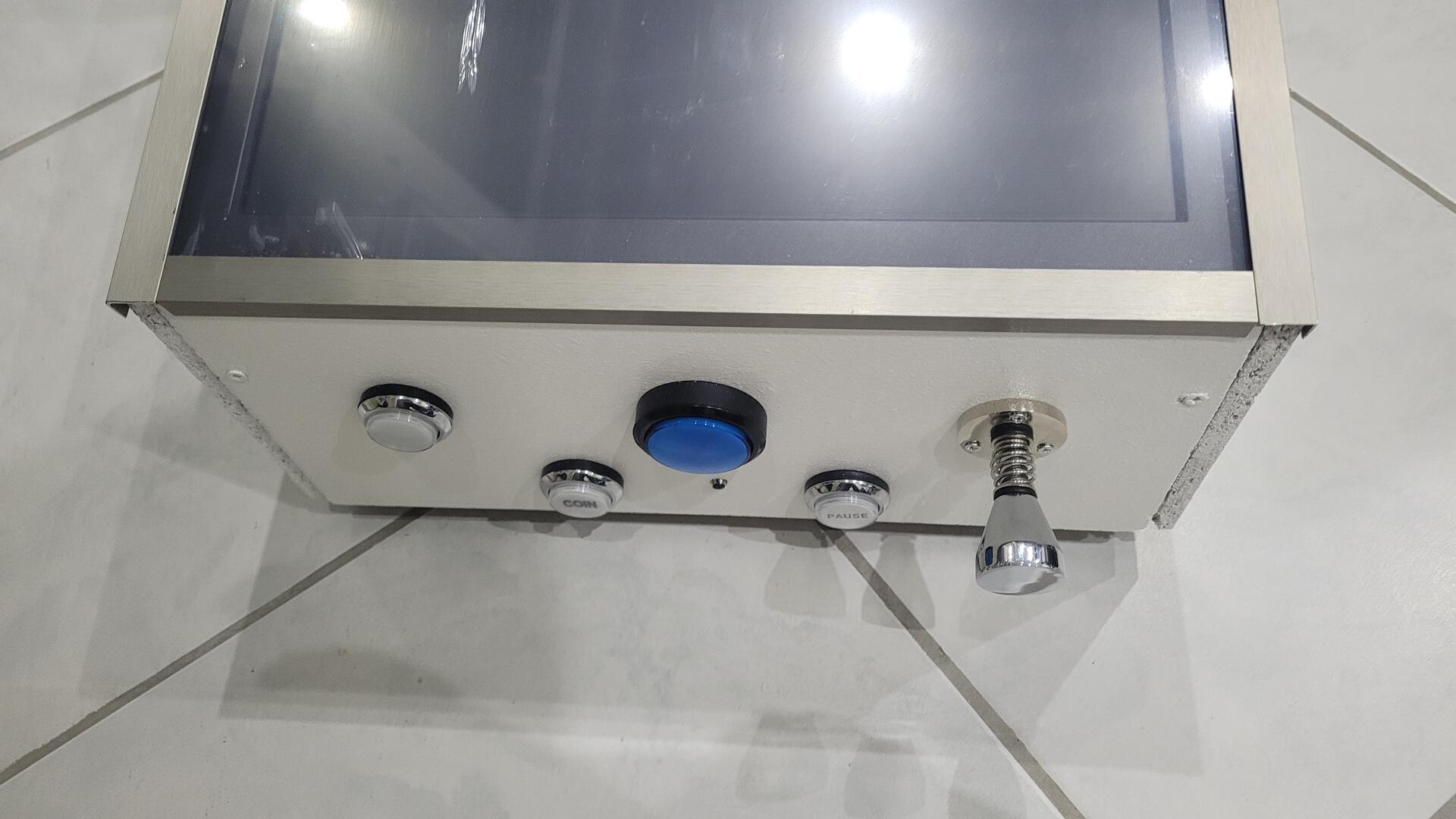
On the front : exit, coin, pause and start buttons as well as the plunger :
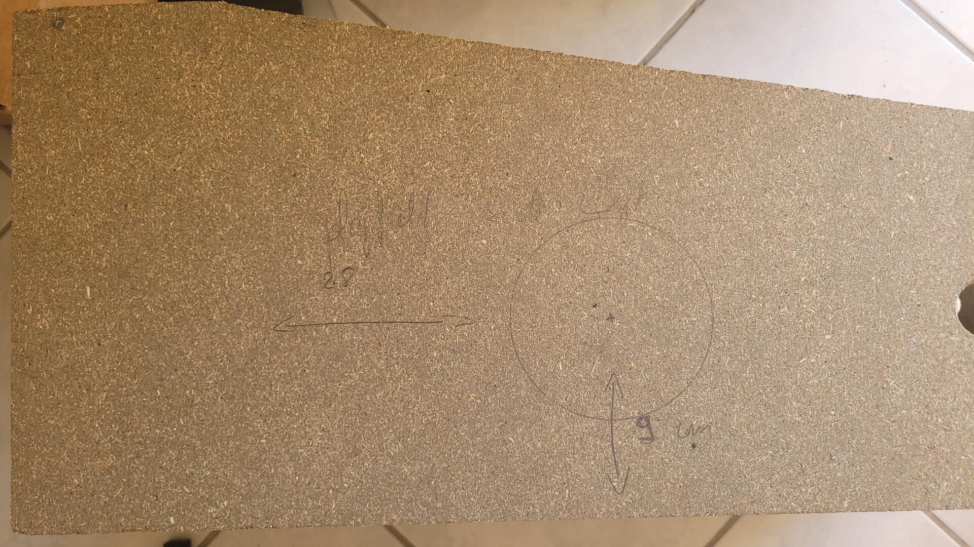
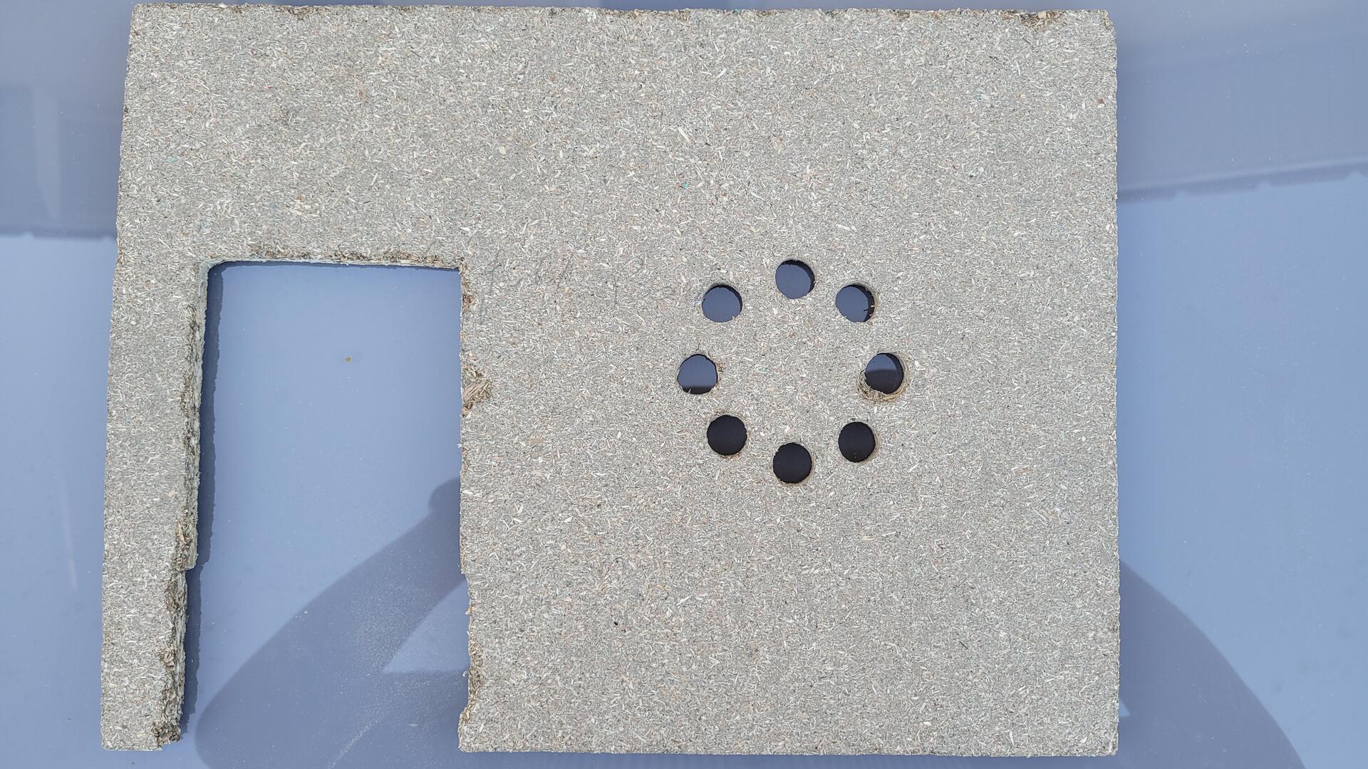
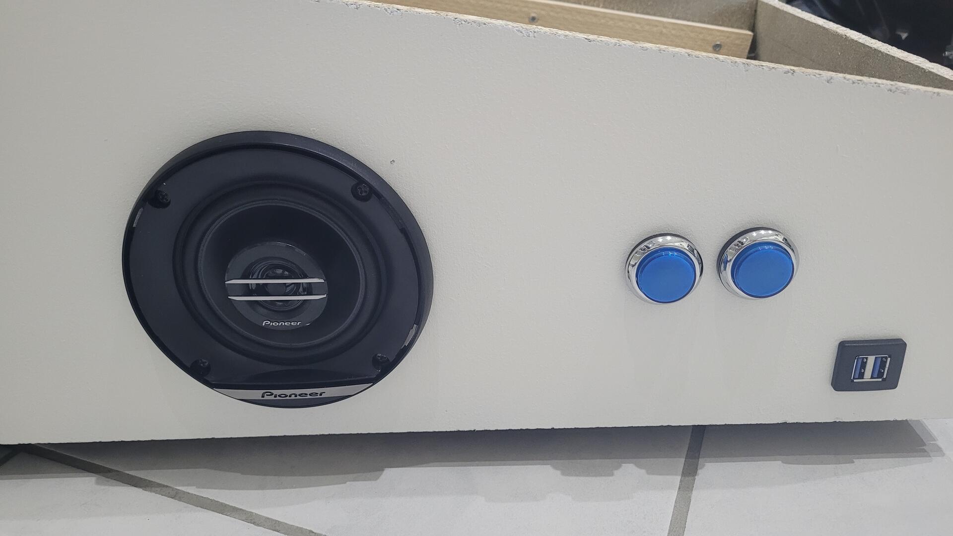
Back on the sides : holes for the speakers (I used a jig saw this time) :
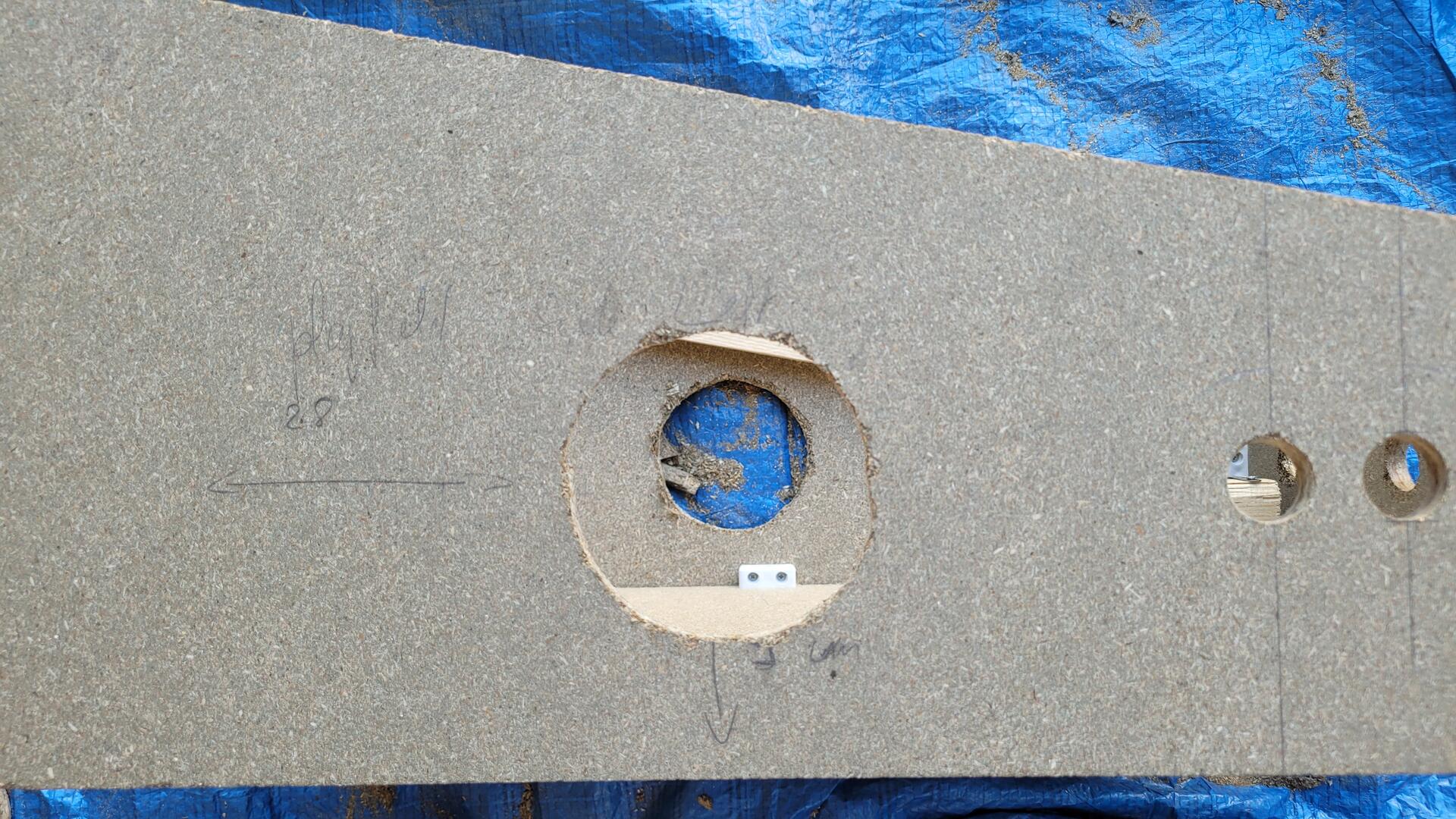
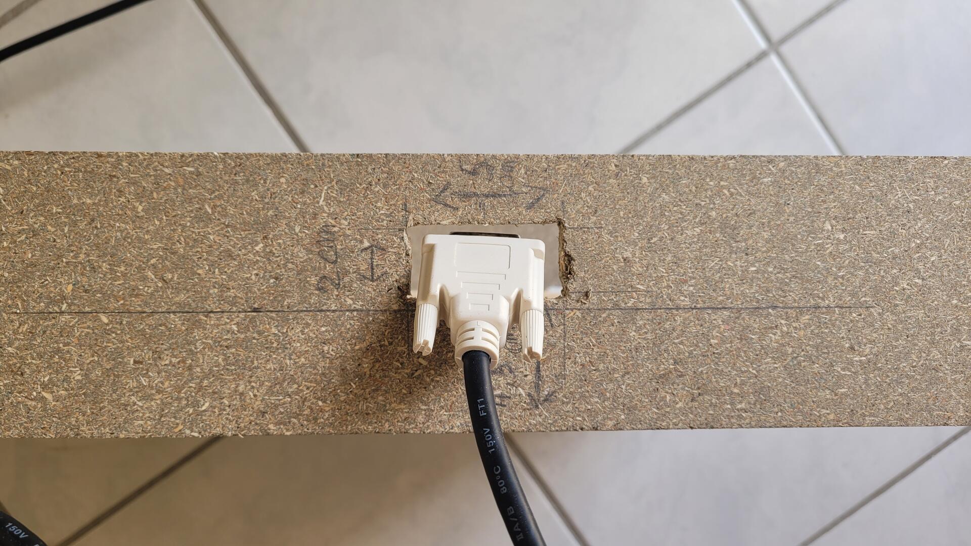
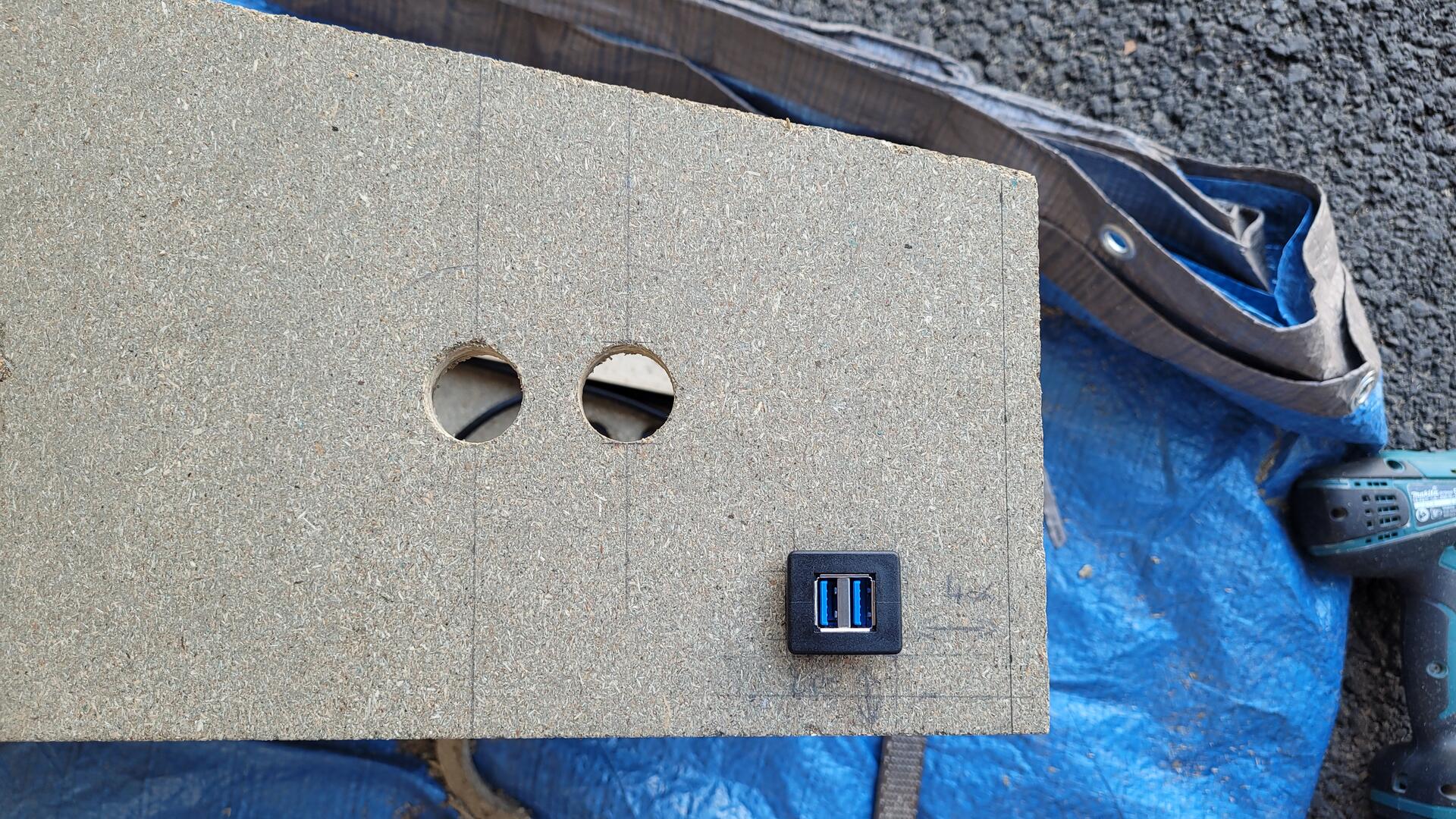
And last but not least : one hole on the right side for two USB ports…
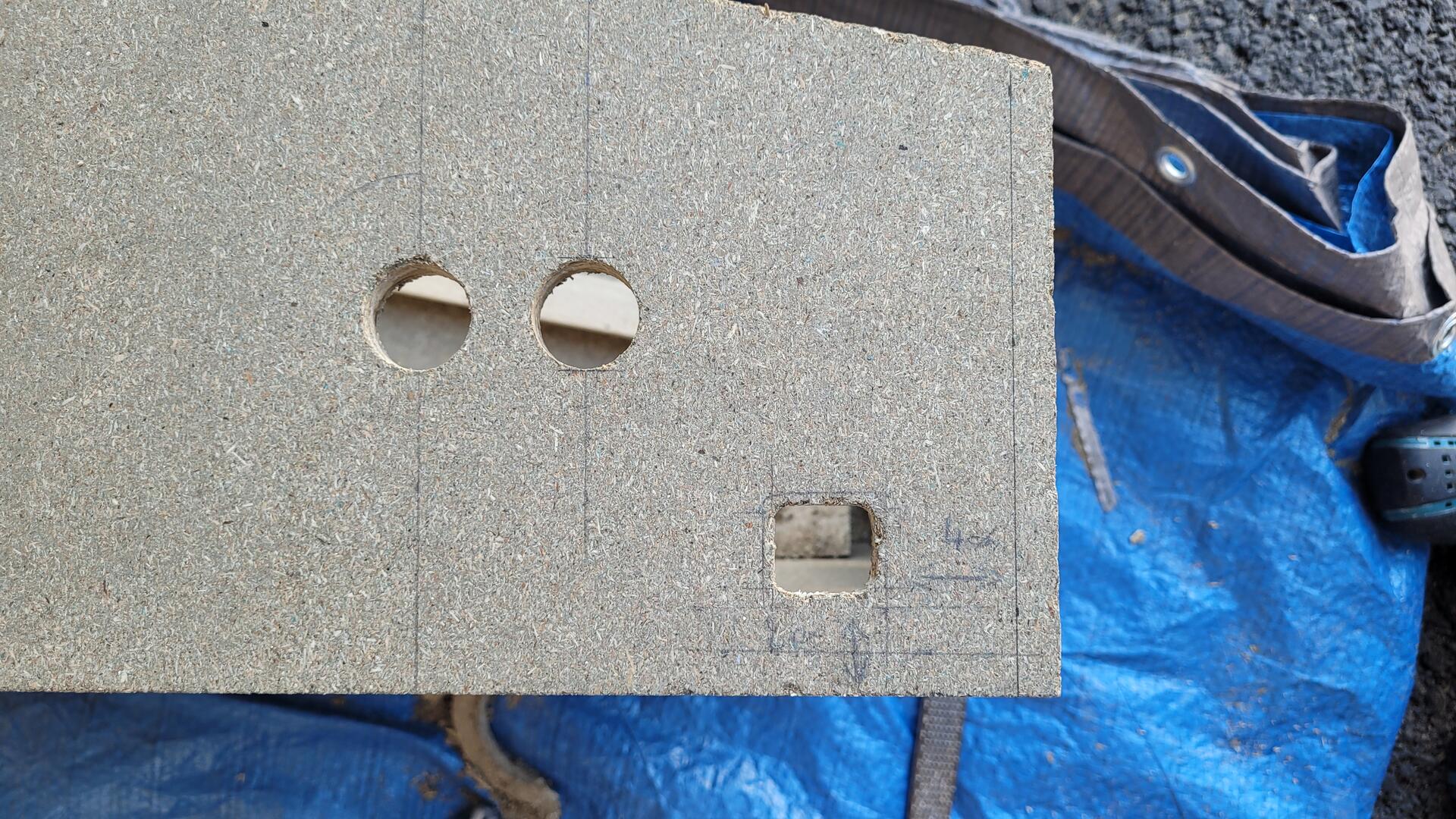
…and another one on the left side for the ATX power-on button (10mm momentary push button) :
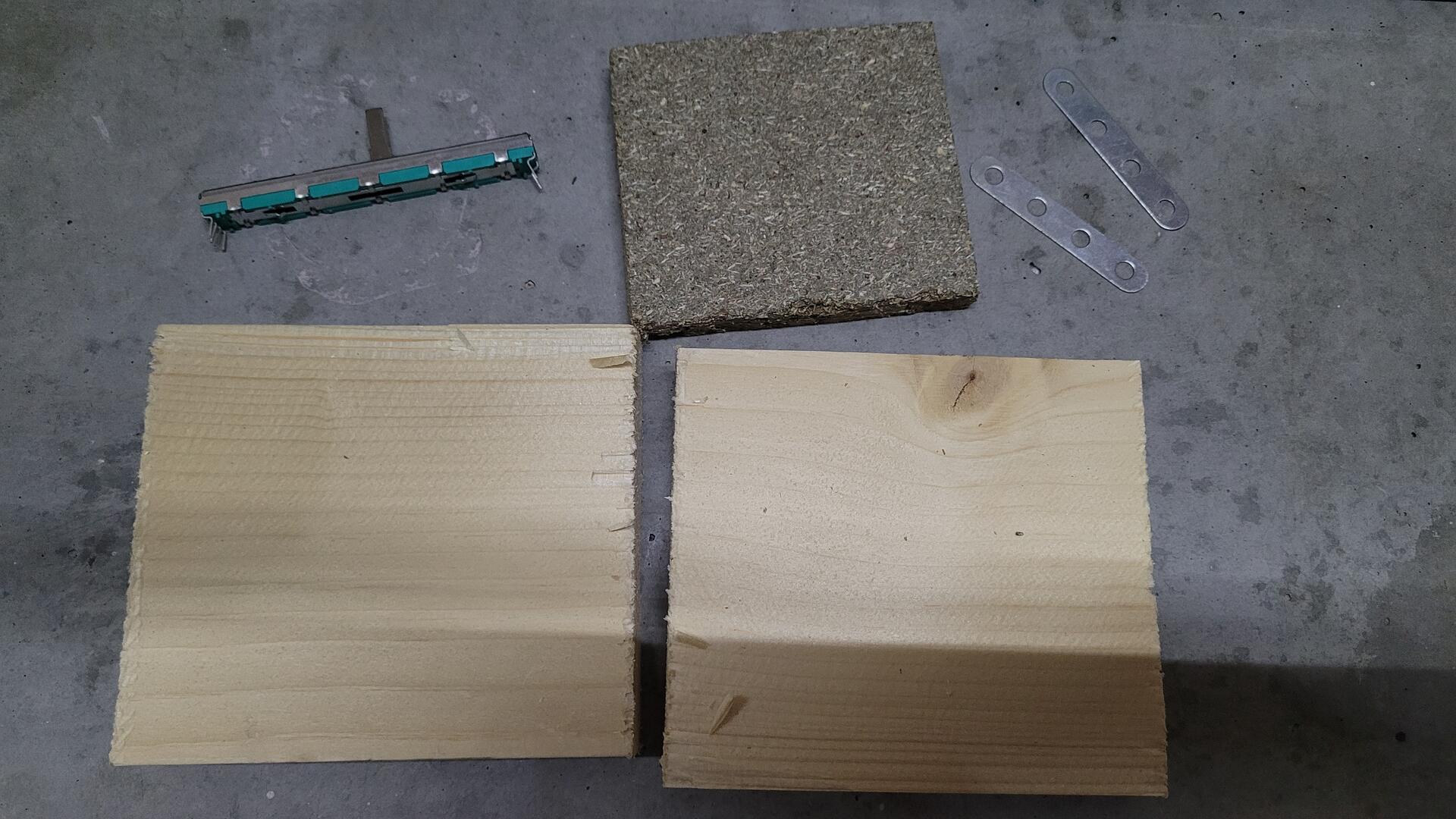
Plunger system
Some “analog plunger” can be bought on Visual Pinball specialist websites, but the one I made is cheaper (less than 17 euros) and more customisable :).
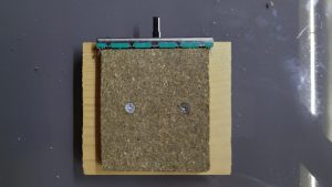
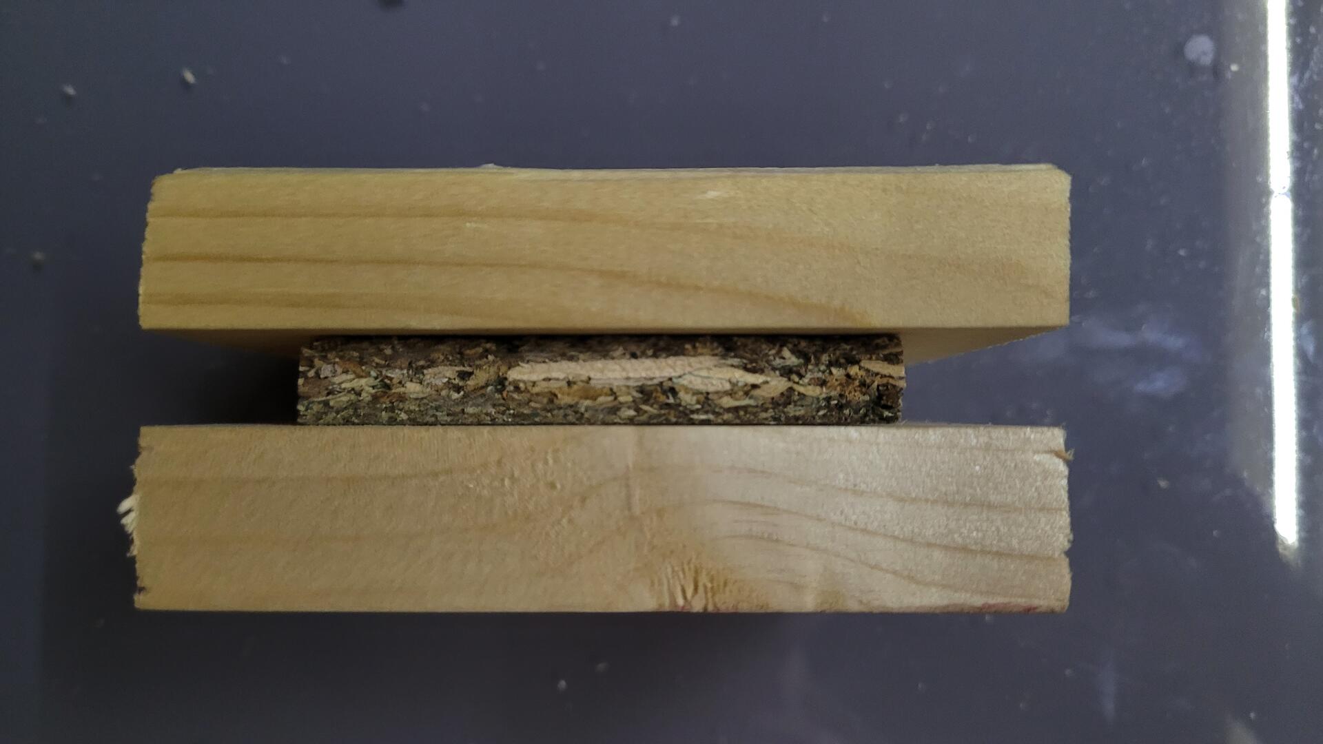
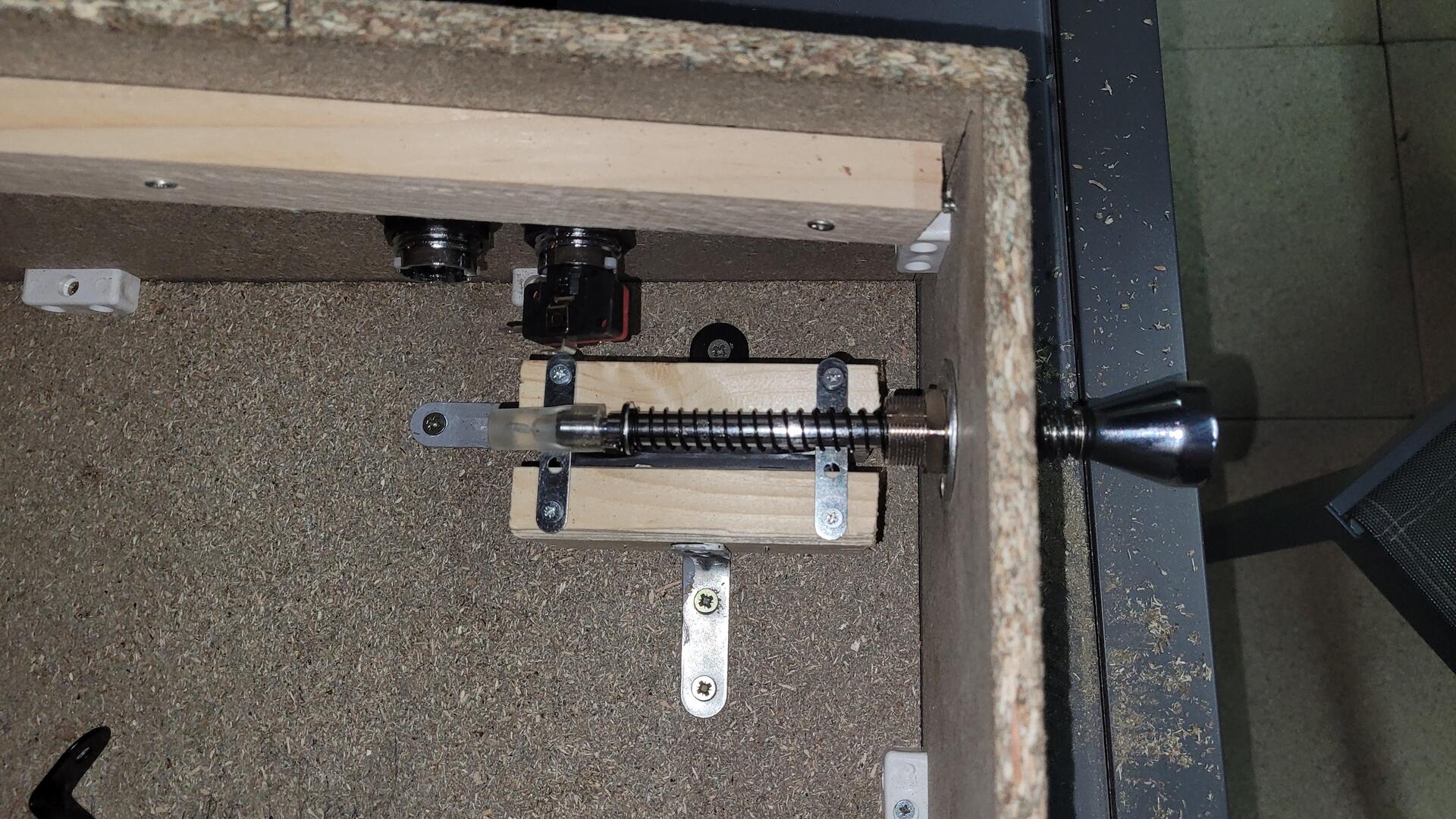
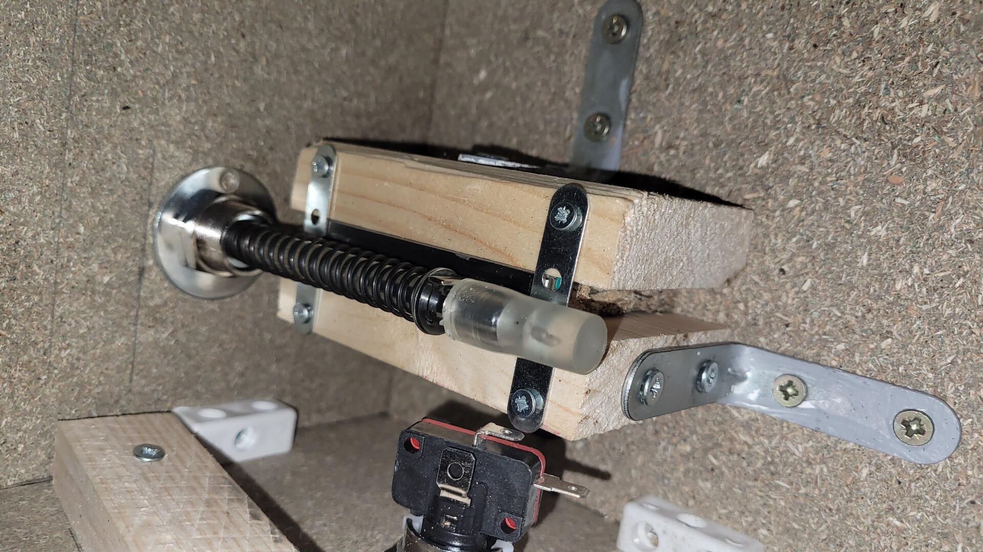
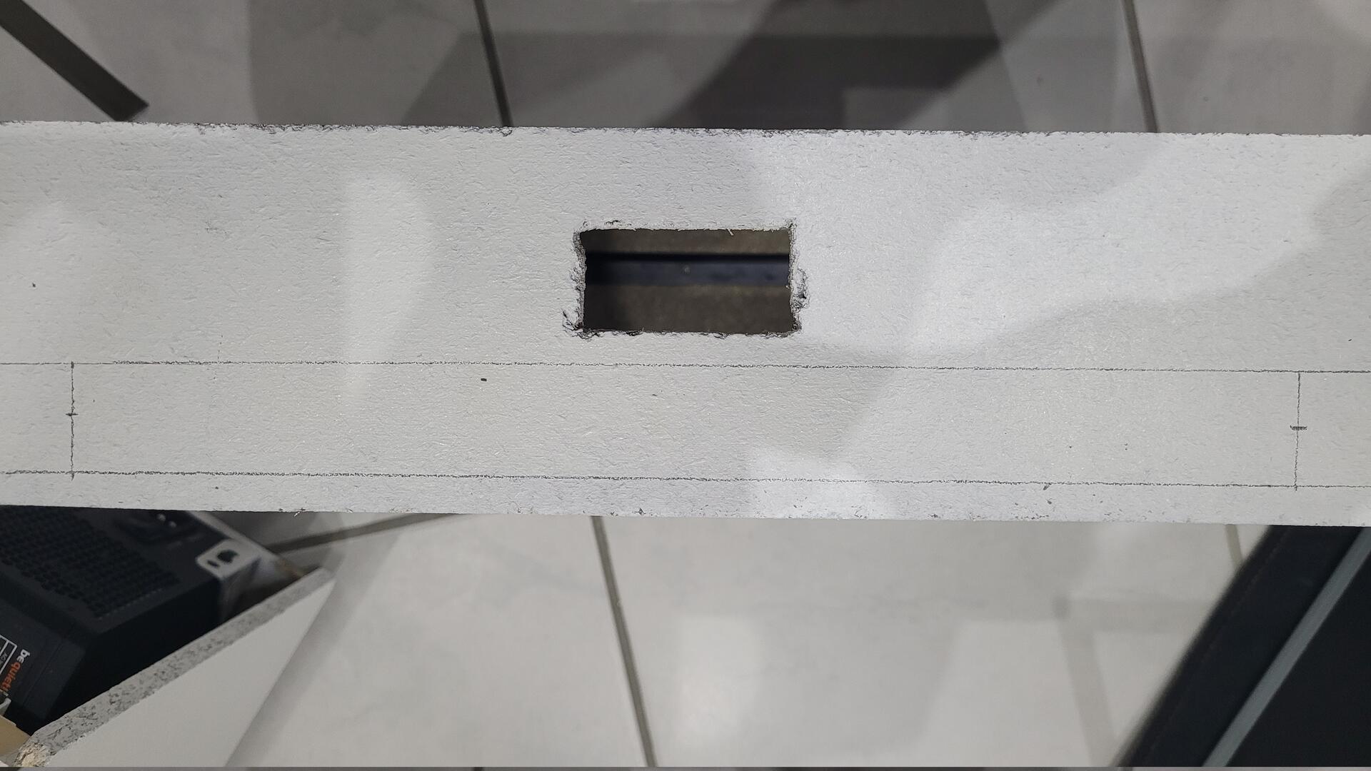
Basicaly, the plunger system consists in a slider potentiometer (fader) moved by a real plunger. However, the potentiometer has to be at the good height and body part must not move while actioning the plunger.
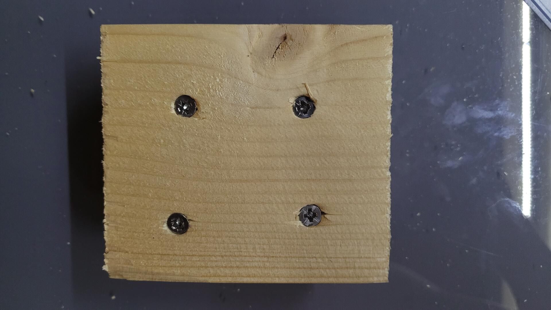
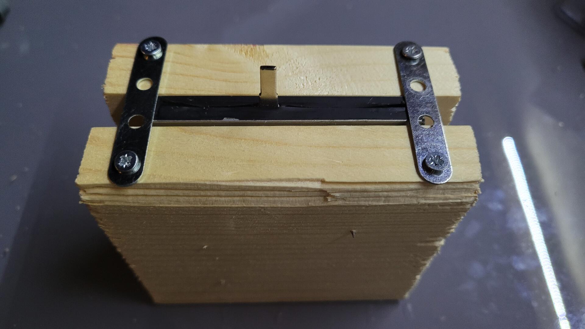
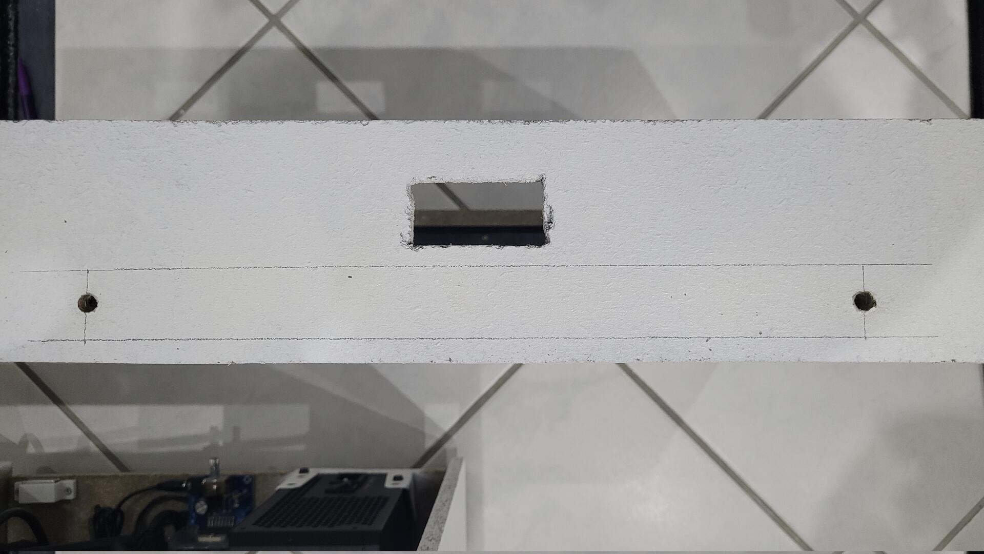
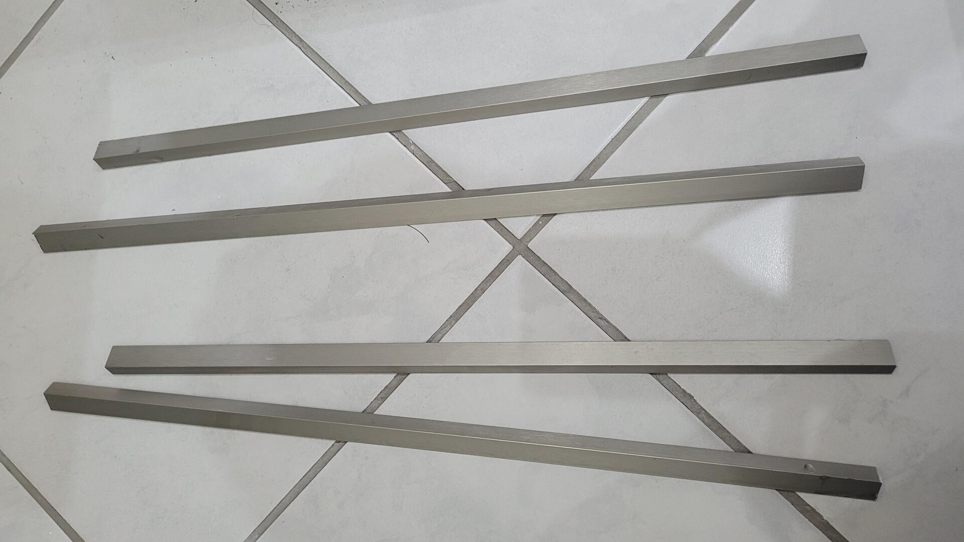
The fixation system is composed of a piece of 10mm chipboard wood sandwitched between two pieces of pine wood. The potentioneter is simply laid on the top and has an overflow of about 1mm regarding the pieces of pine wood. Then two metal bars are screwed over on each side, so the potentiometer body can’t move and the slider is totaly free. Also, the legs are still accessible to solder some wires.
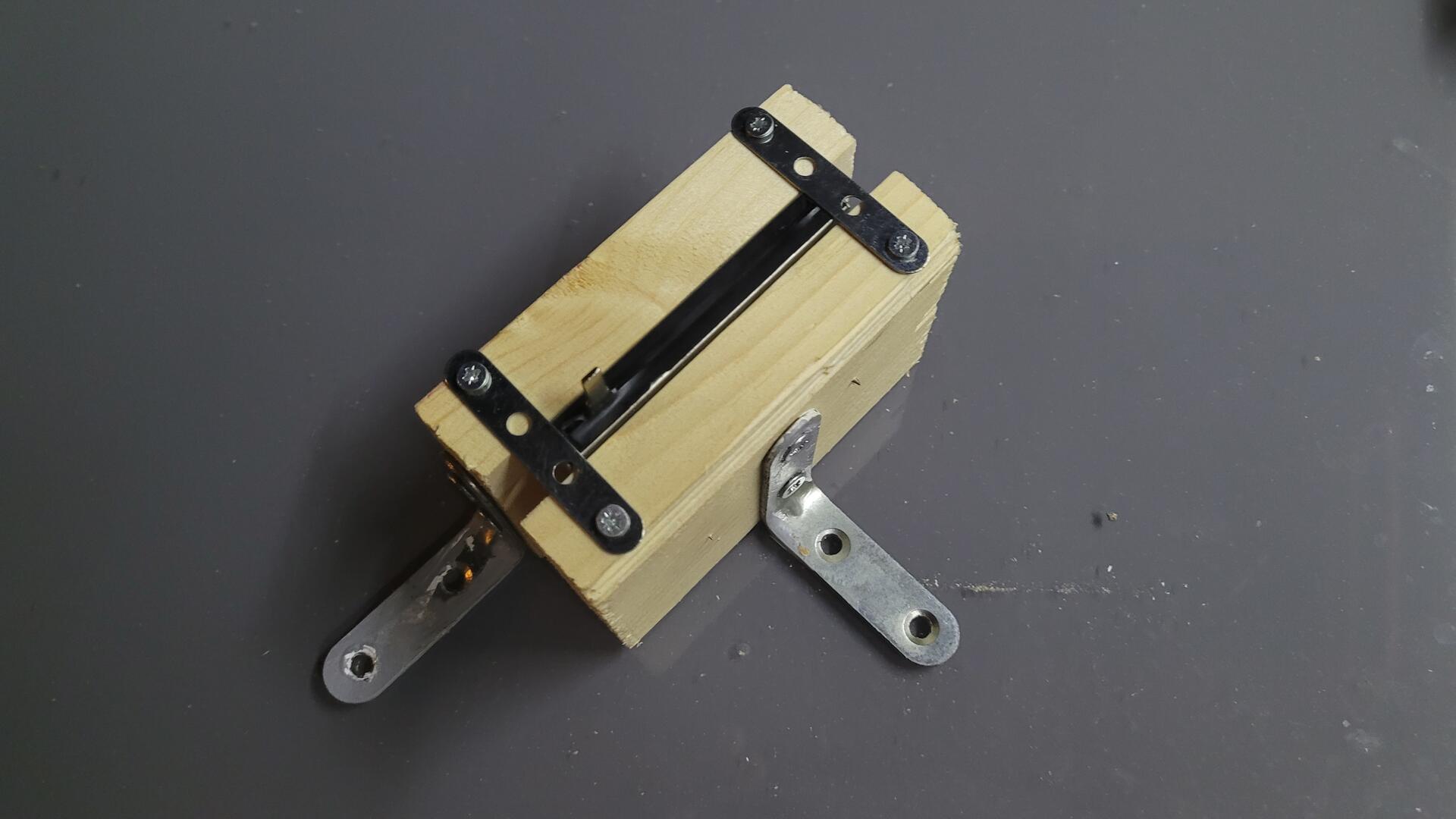
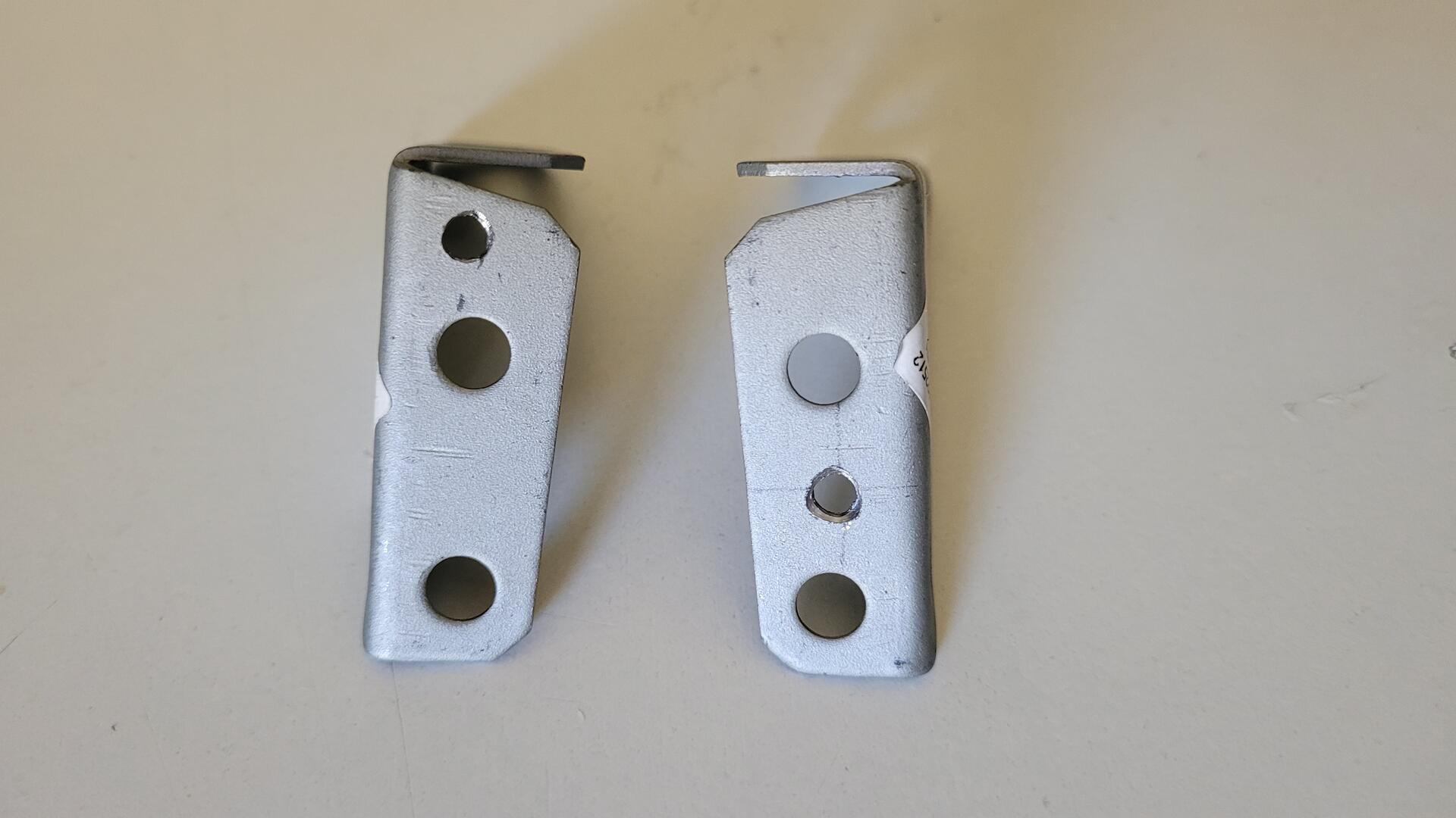
Then, I used two metal squares to fixe the structure inside the cabiner.
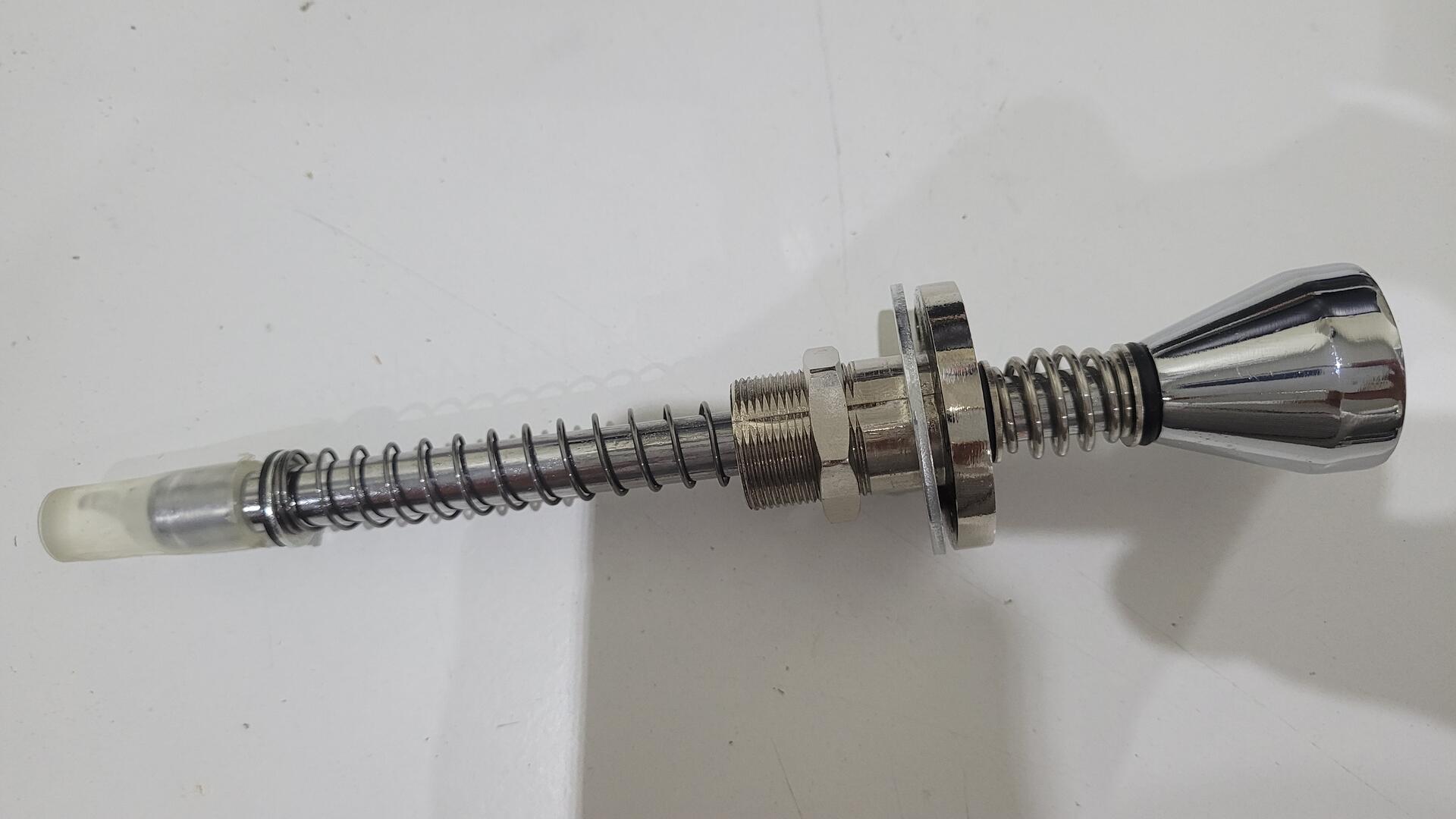
The whole thing mounted inside the cabinet : the slider is swandwitched between the metal ring and the plastic sleeve :
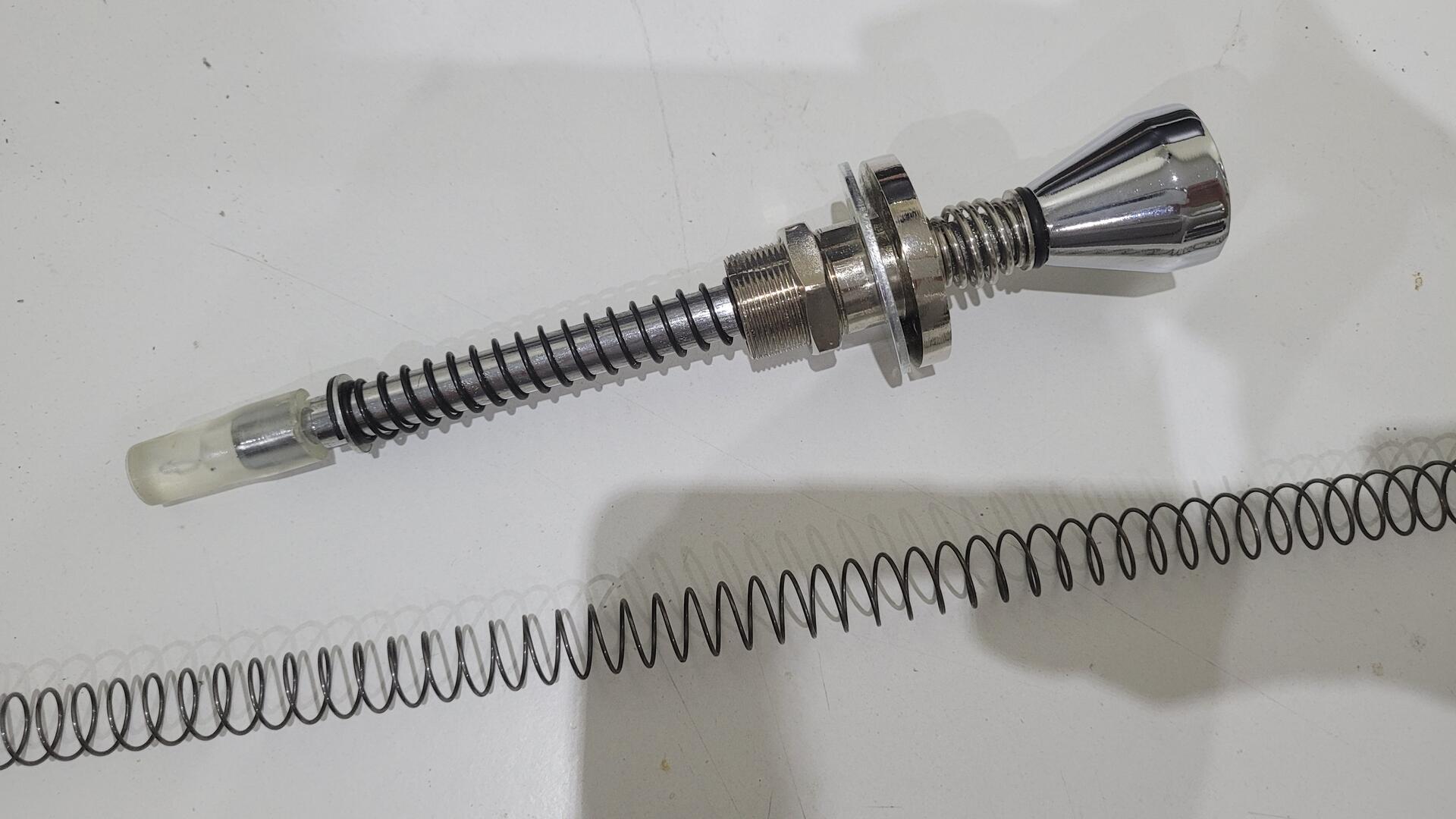
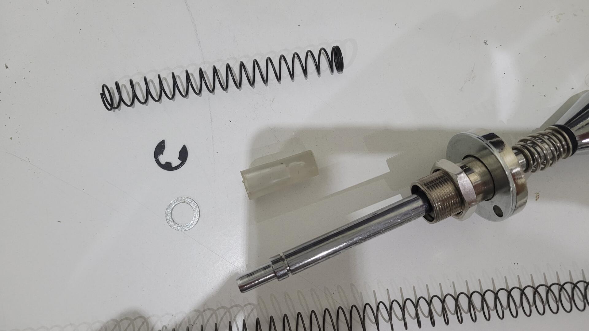
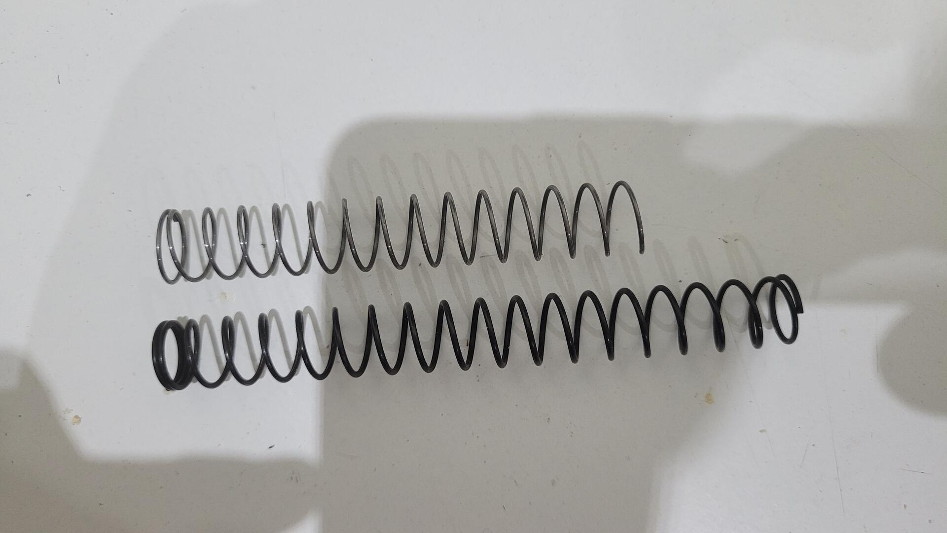
As I used a plunger made for real pinball, the spring was very hard. In fact, when I tried to pull it, the whole cabinet was coming ! So I replaced the original spring by a softer one. I used a 0.8x12x305mm spring that I cut a bit shorter than the original. The result is a nice plunger that can be pulled quite easily, but still react fast enough to simulate a real plunger with the potentiometer.
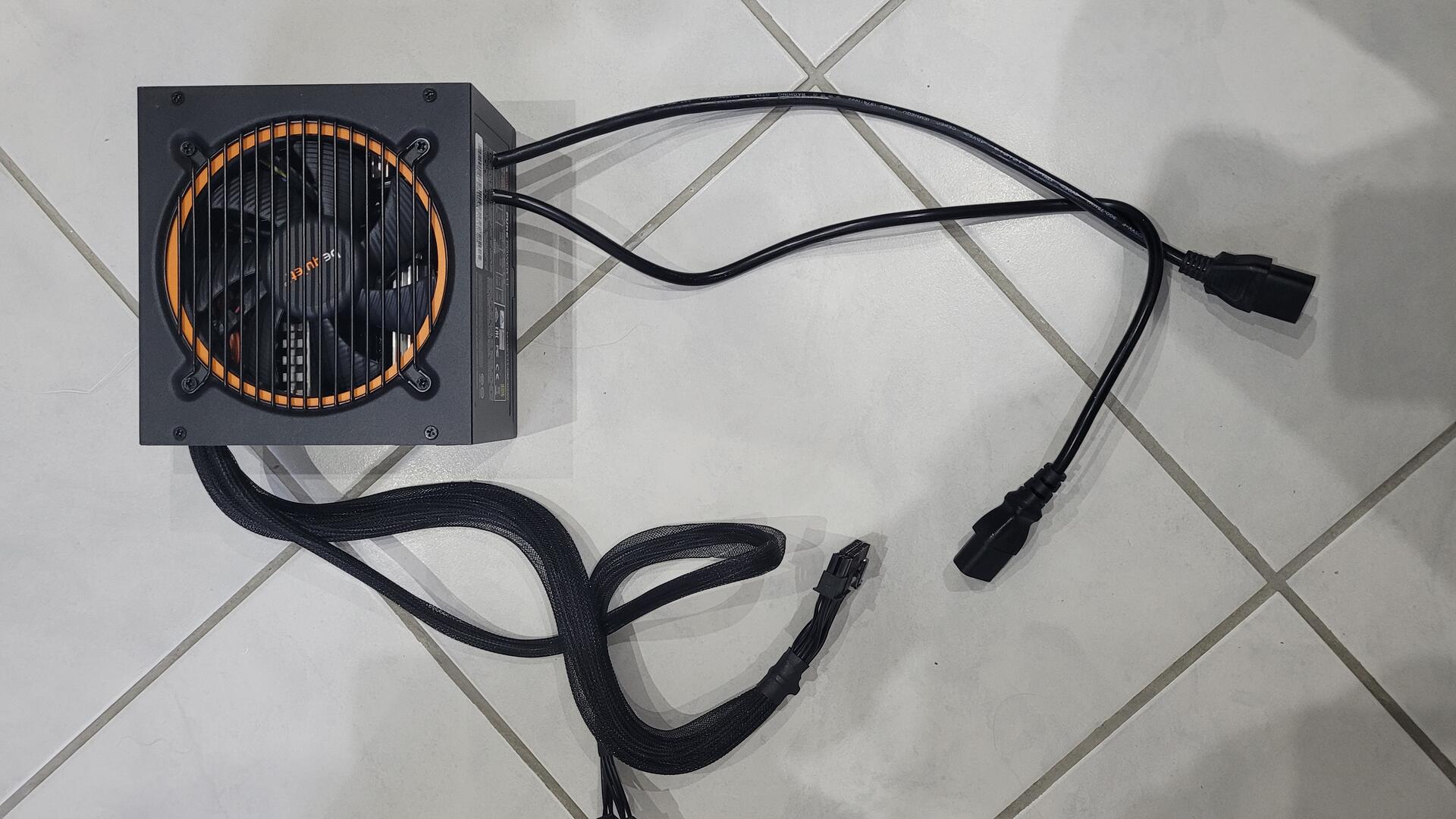
Power supply supports & mod
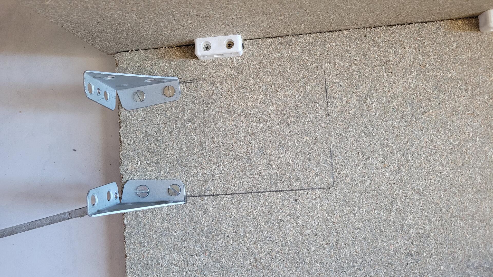
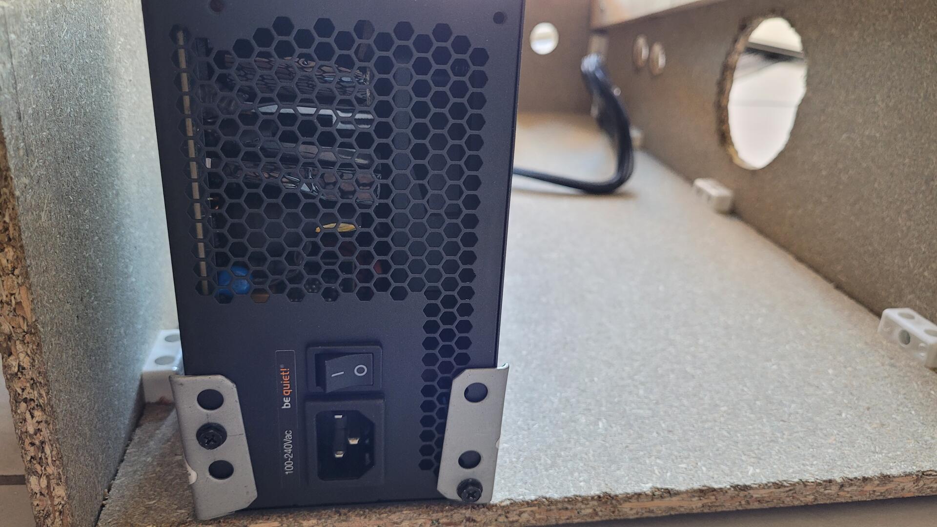
For a matter of space, the power supply must be mounted vertically. I could not fix in on the back pannel because I wanted to make it easy to open. So I used some kind of metal square that are normally used in carpentry. I did a hole in each to be able to screw the power supply on them.
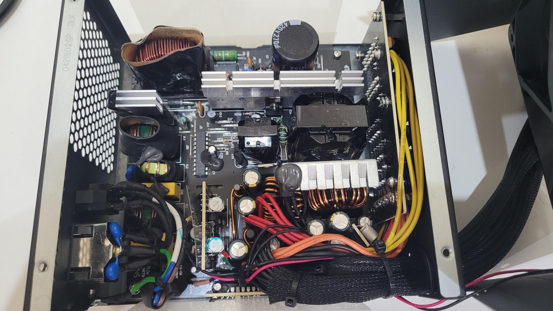
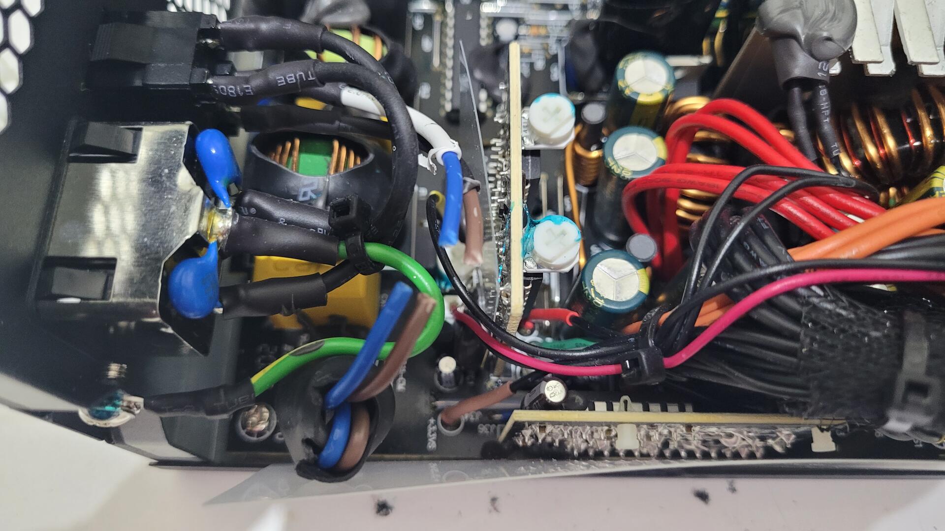
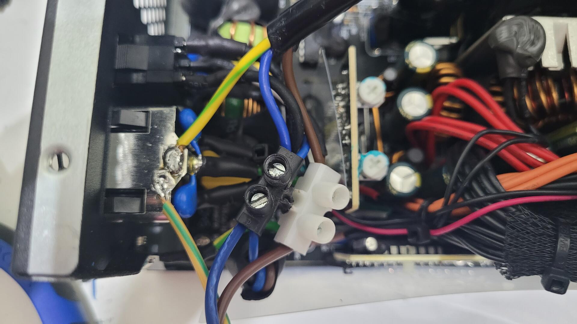
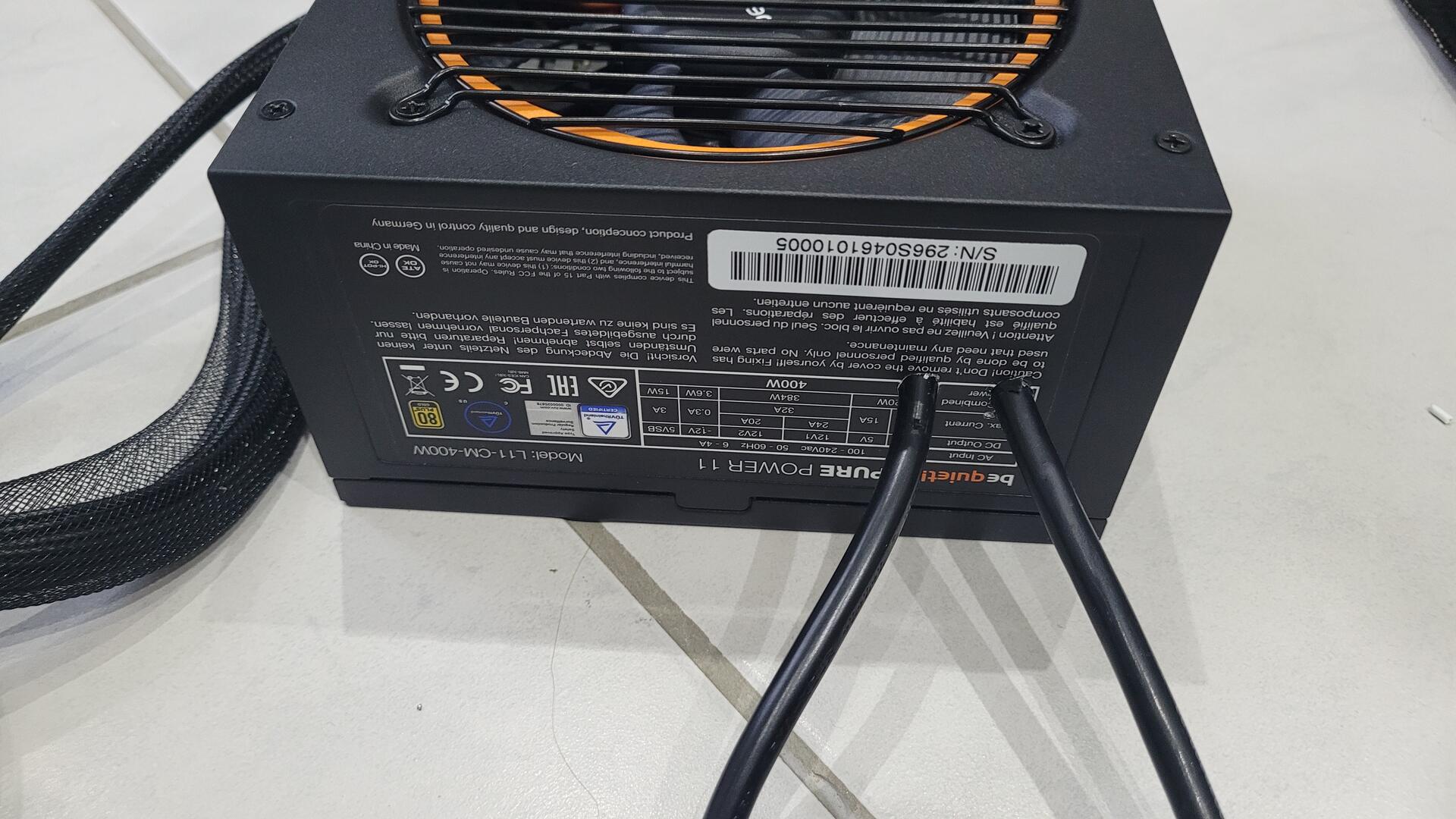
The power supply provides current for the motherboard, but the two LCD pannels also needed some juice. In order to get only one plug on the back of the canbinet for all, I modified the power supply by adding two additional c13 cables directly at the source. Two holes are drilled in the metallic shield to pass the wires
Playfield backdoor
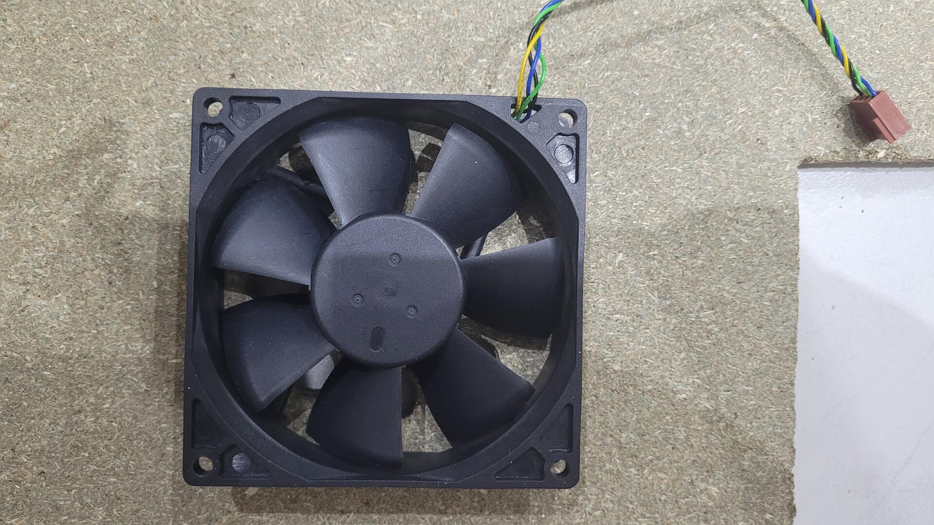
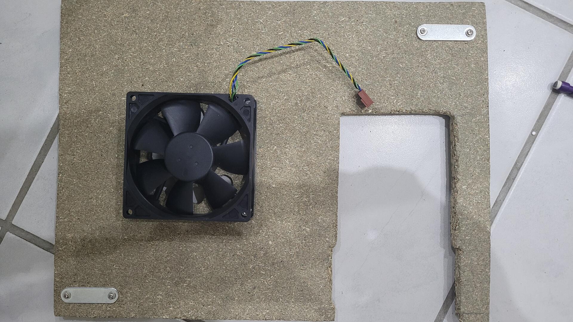
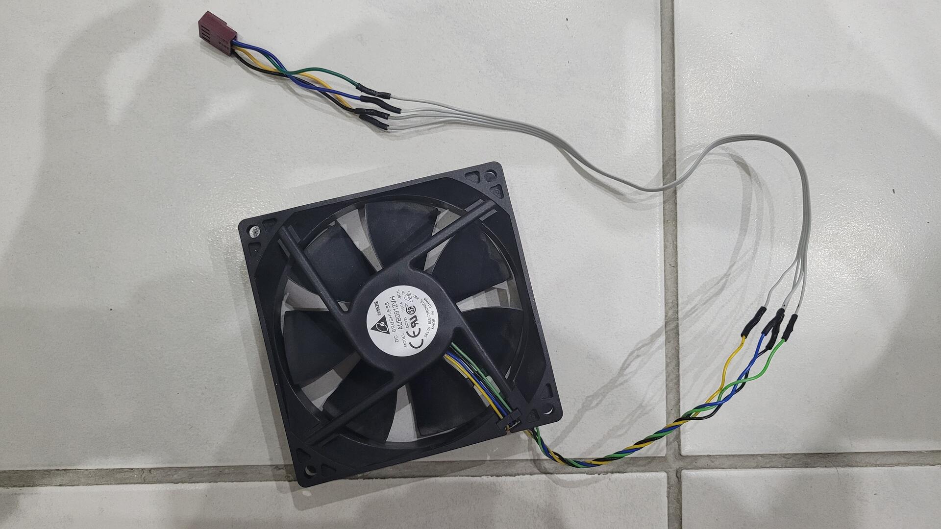
As a lot of things generate heat in this small cabinet (2 screens, cpu, graphic card, audio amp…), I added a standard 100mm fan to the playfield backdoor.
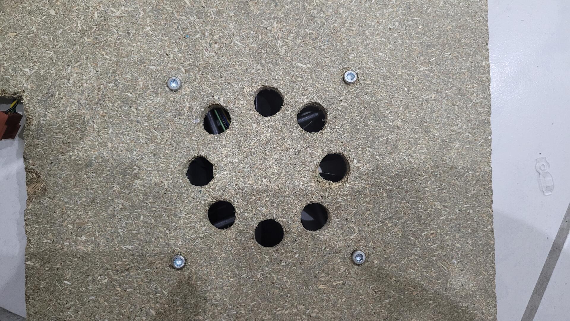
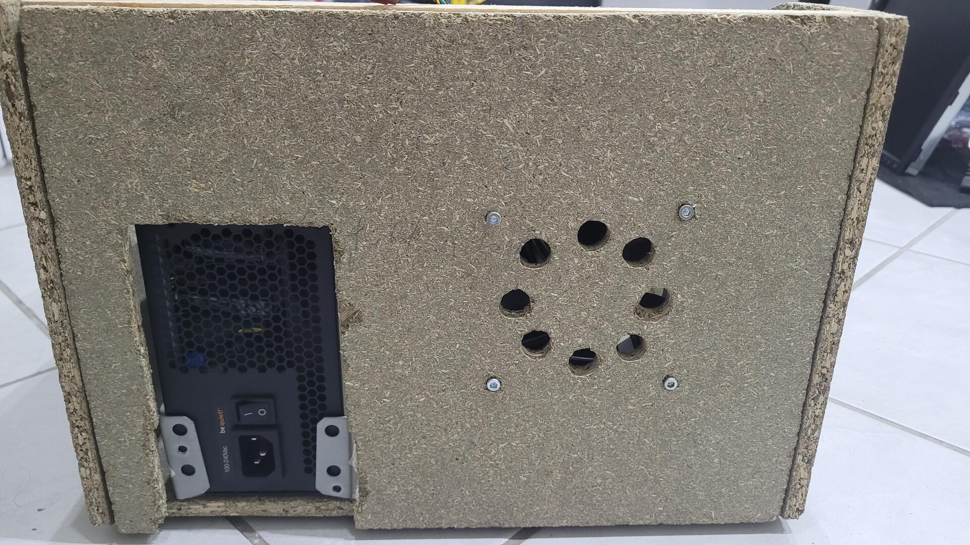
As I said earlier, I wanted the backdoor to be removable, so I could access to the inside even with everything in place. The simplest way I found was to use two closet door magnets on two corners. The backdoor is then simply held by the magnets.
The hole for the power supply is not the prettiest part, but it’s in the back, and is rarely seen.
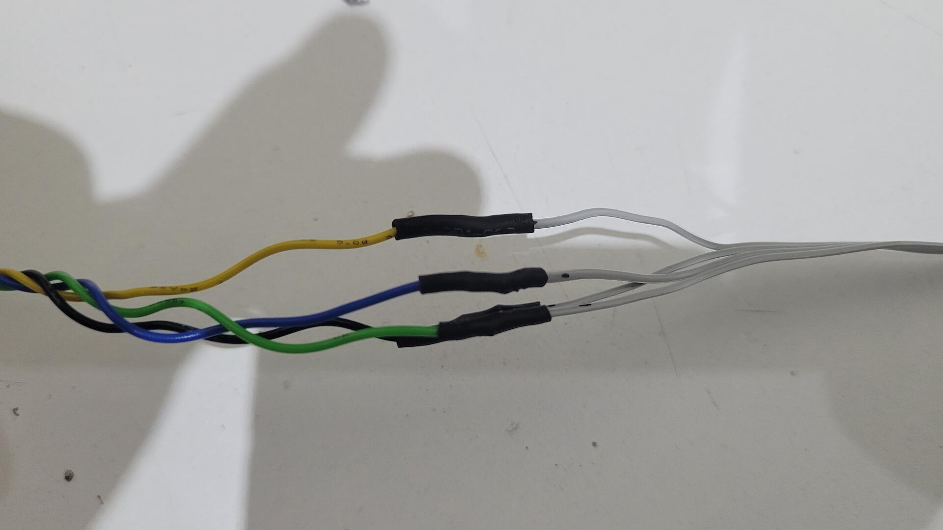
The backdoor being removable, I had to make the fan’s wire longer to reach the motherboard connector.
Motherboard and Graphic cards
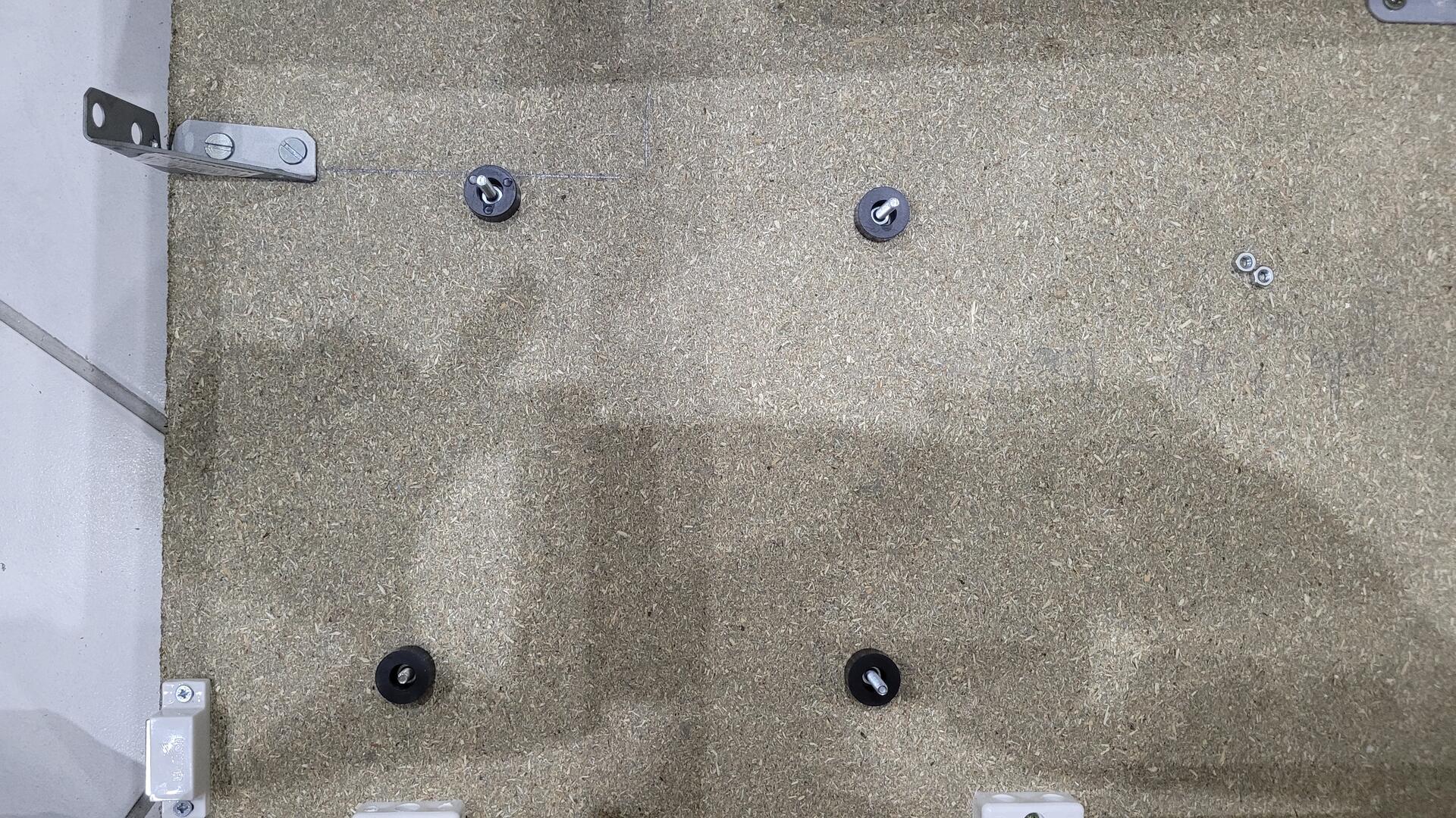
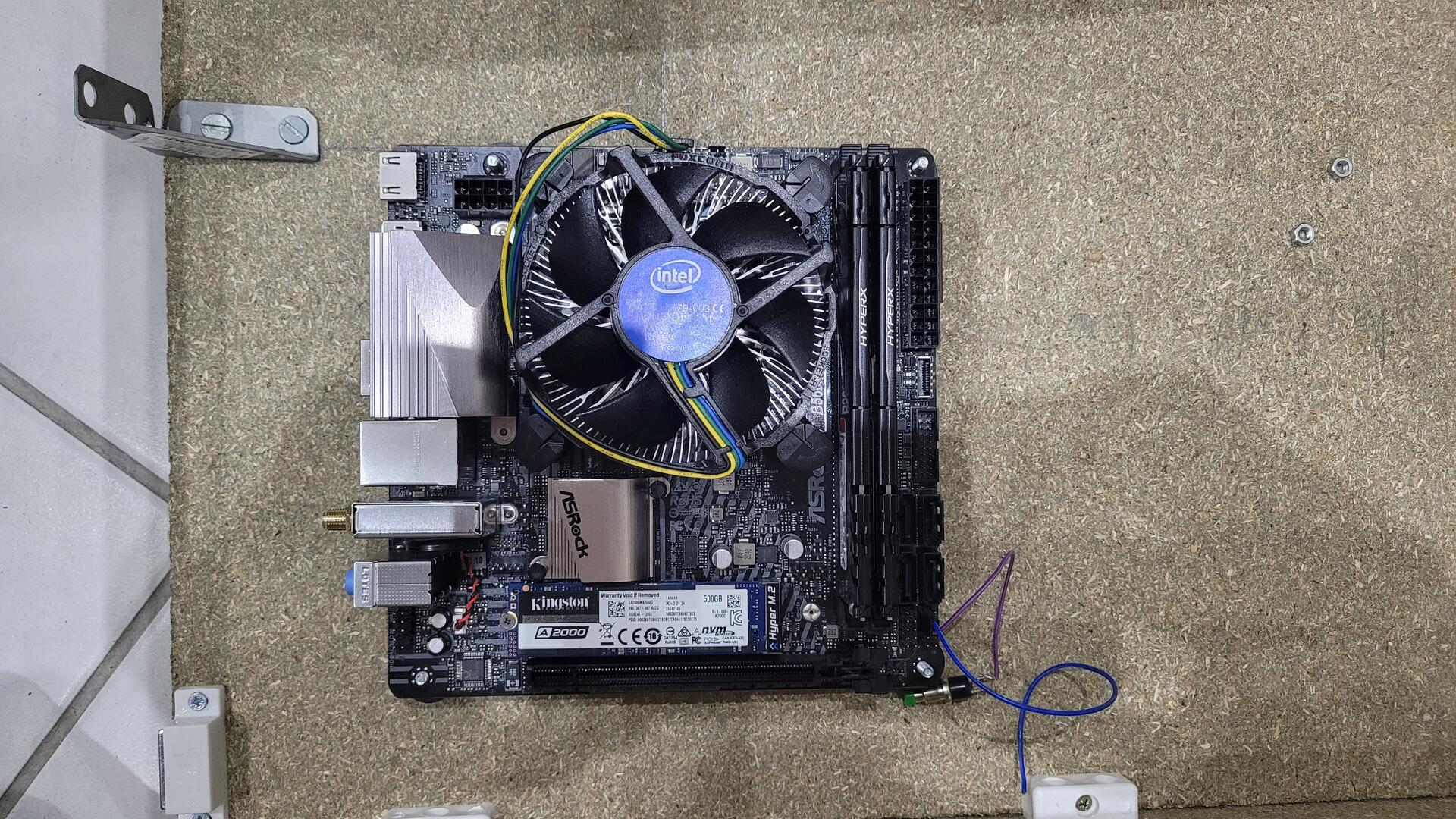
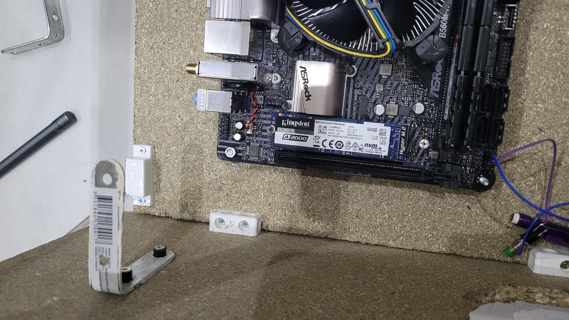
The motherboard is fixed using screws from the bottom of the cabinet. The screws are fixed with bolts on the cabinet. The motherboard is laid on plastic washers, and other bolts maintain it. The plastic washers prevents the motherboard from touching the woods (air flow).
The graphic card take its support from a metal square screwed in the wood and is placed far enough from the side to let the air flow for heat dissipation.
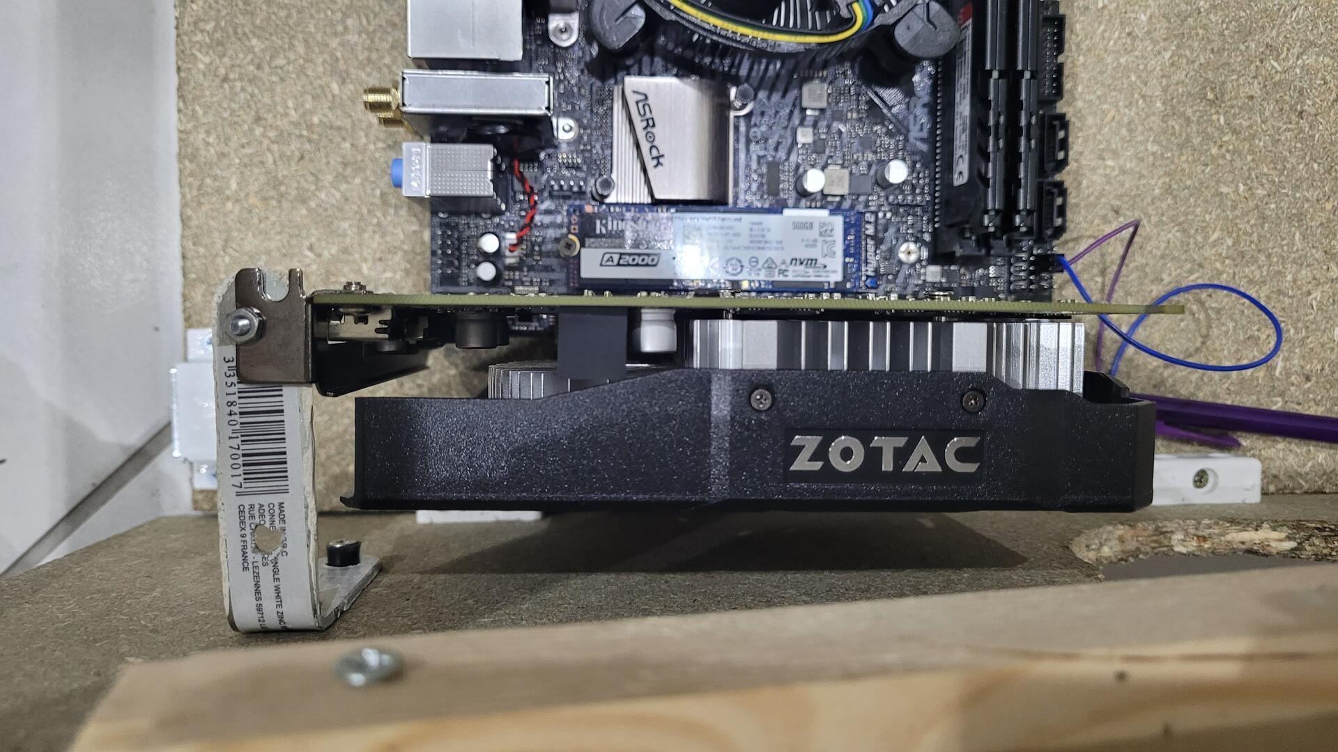
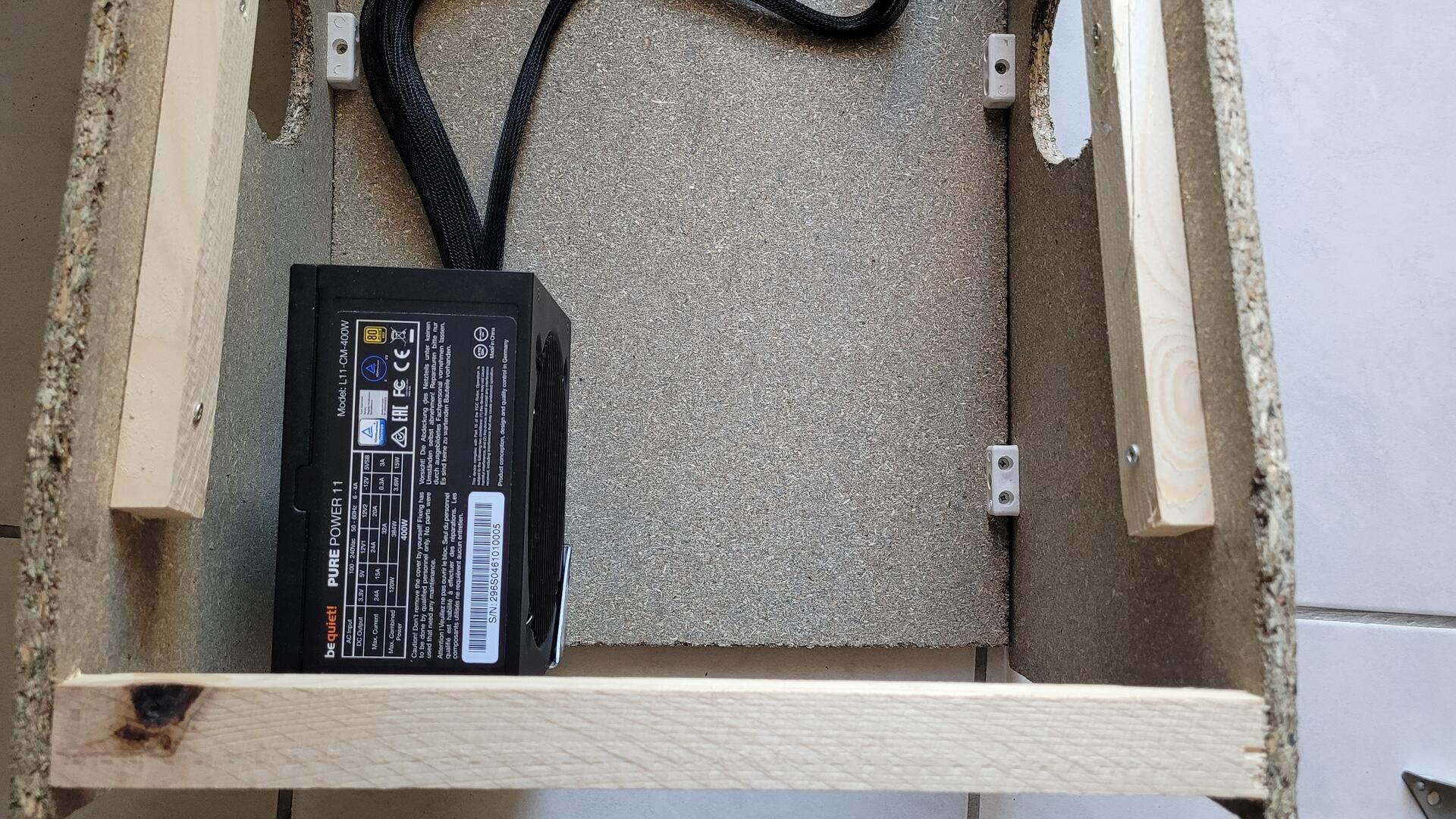
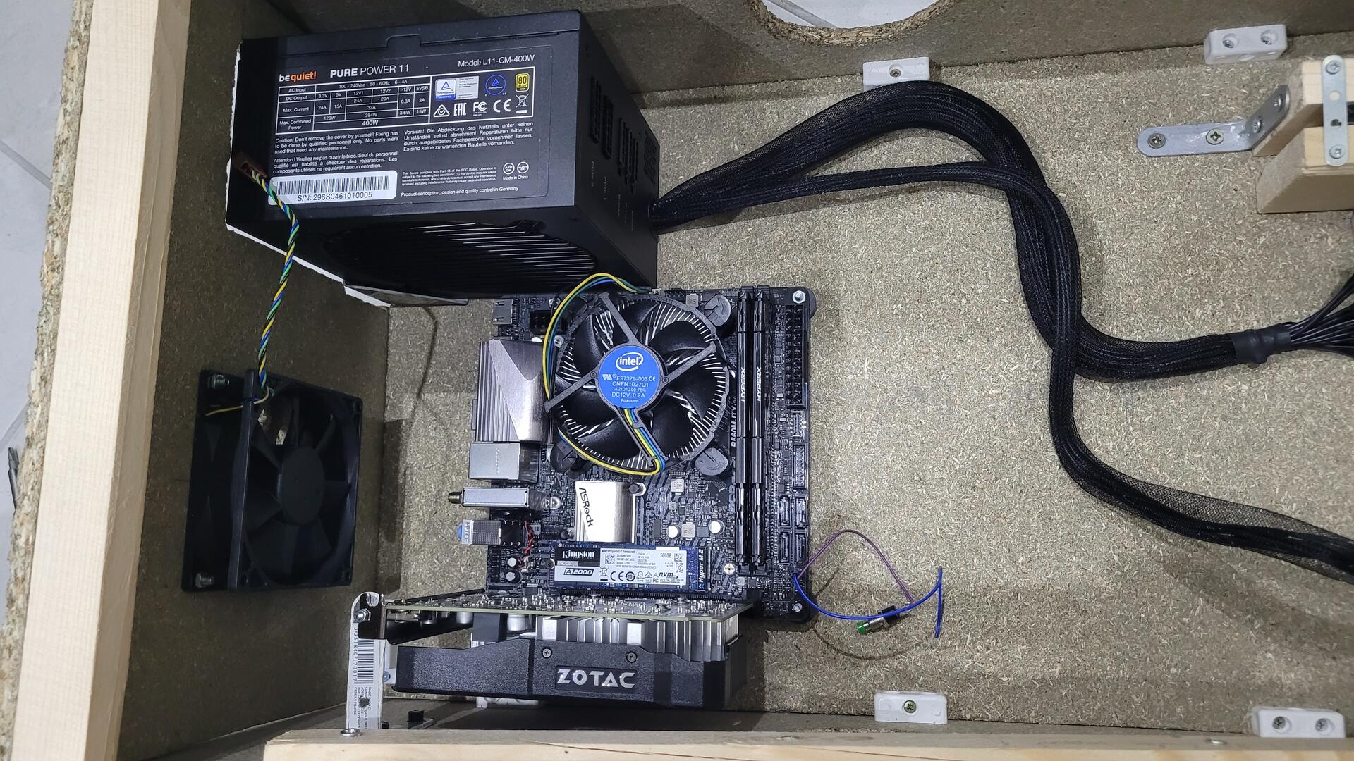
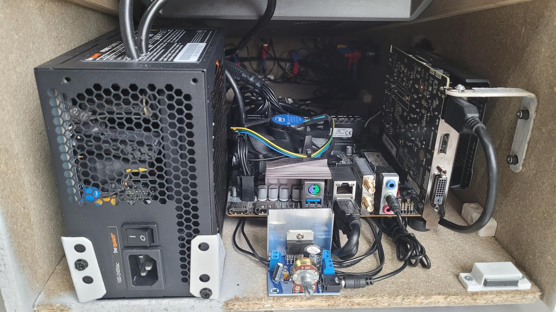
Here is an overall view of the power supply, motherboard and graphic card mounted into the cabinet :
Audio Amp
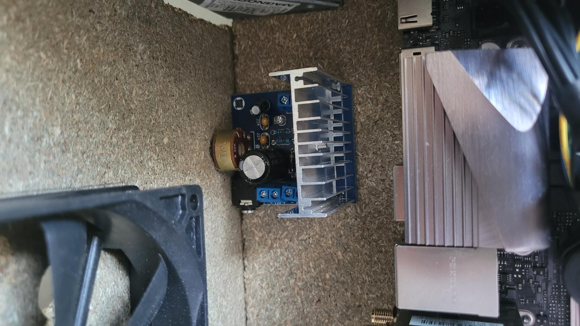
A pinball game is nothing without a good sound system. The numerical amplifier has been screwed on the back of the cabinet (to the left of the power supply and below the fan), so the volume knob could be accessible. I was surprised how well the TDA7297 drives the pair of Pioneer car speakers and the cabinet serves as a nice subwoofer when all is closed.
Paint / buttons / speakers
Before painting, I put some protection adhesive over all holes in order not to paint all the inside (skrews, etc.)
I had to use a bit less than 3 x 400ml spray paint for the whole cabinet. Maybe standard paint with a good brush could have been cheaper. However, spray paint has a very good finish…
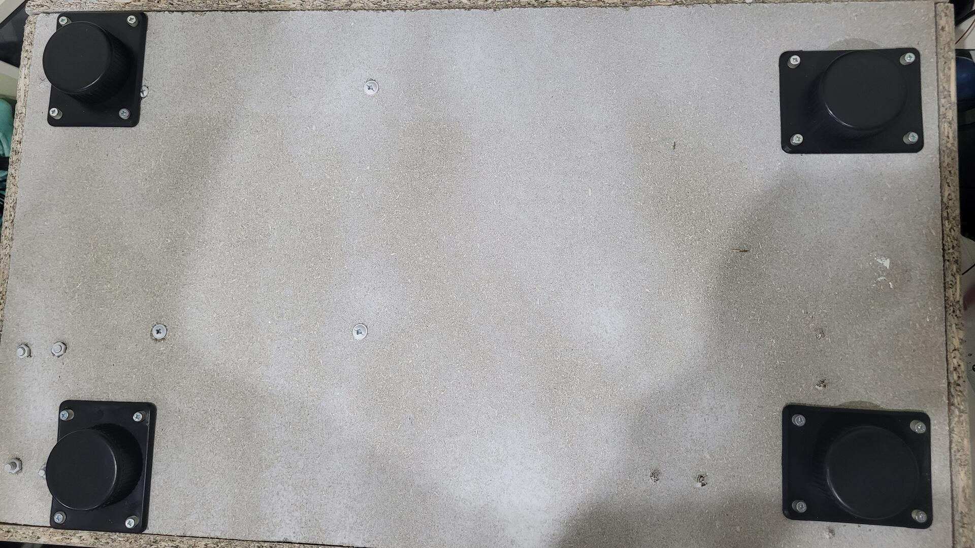
The bottom of the cabinet has only had one layer of paint because I did not see any interest in making it “perfect” has it’s the bottom which is never seen. Note that I added 4 small plastic legs with ajustable height. This makes the pinball more stable whatever the surface it is on.
At this point, I mounted all the controls, the speakers, the usb port (on the left) and the power button (on the right). The small hole bellow the big blue button host a 3mm blue led inside its metal bed (directly inserted in the wood)

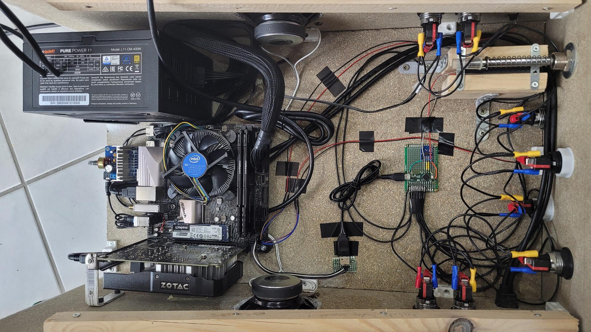
Controls brain
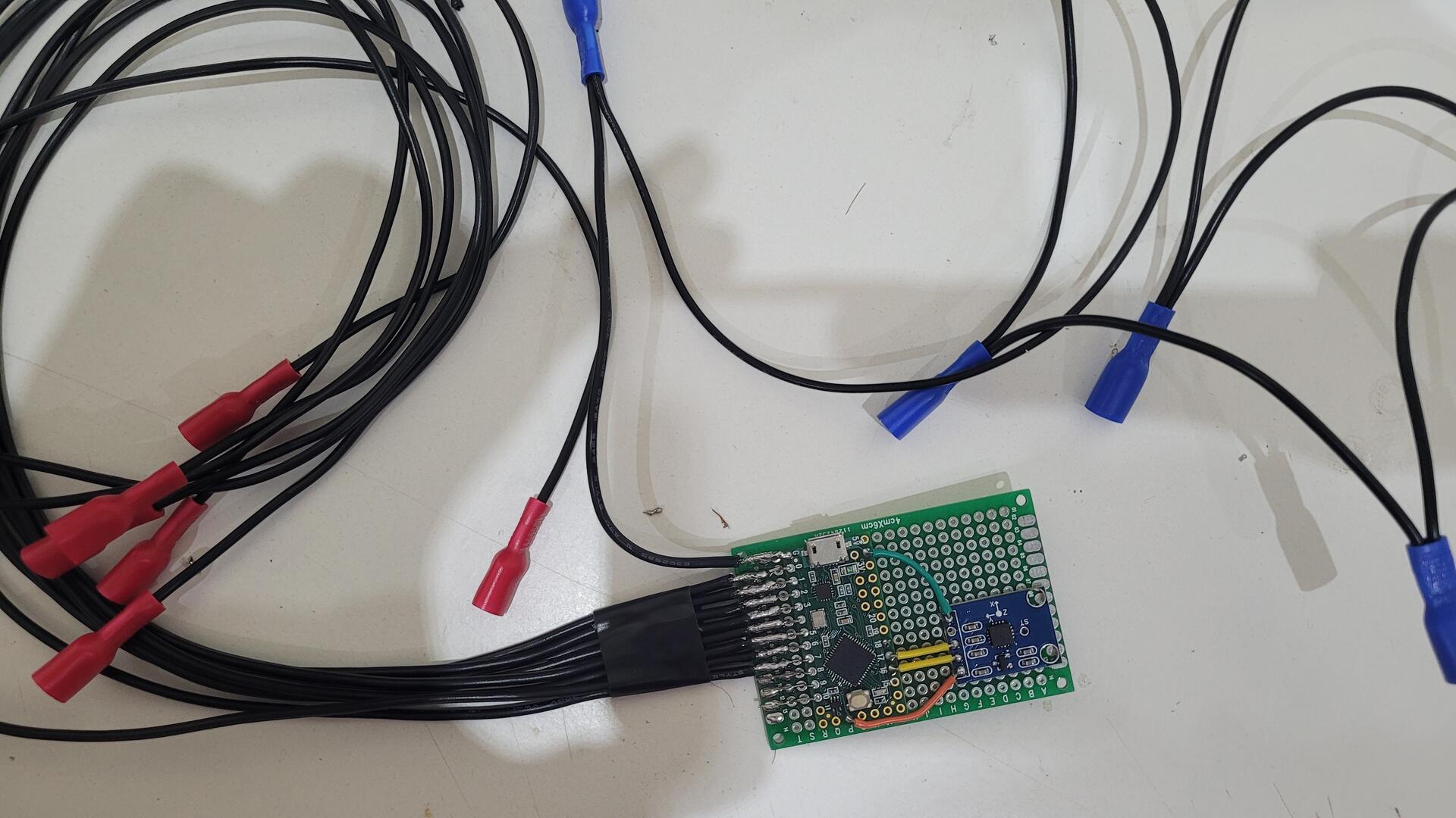
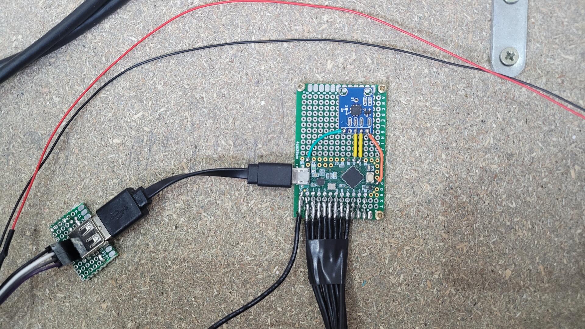
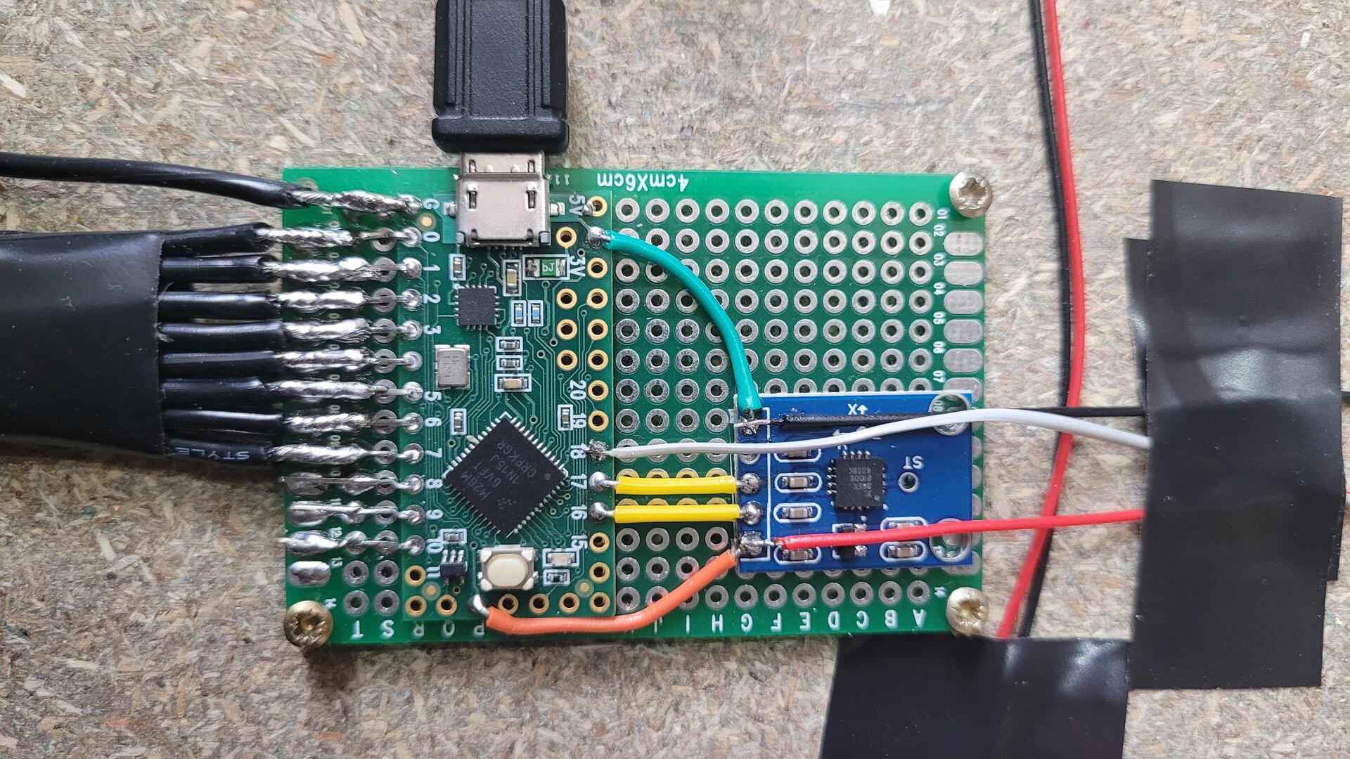
The “brain” that drives all the buttons is based on a Teensy LC to expose a standard HID joypad input to Windows (more on that in the “Software” chapter bellow). An accelerometer (ADXL335 GY-61) is wired to it via 2 analog inputs to handle tilt.
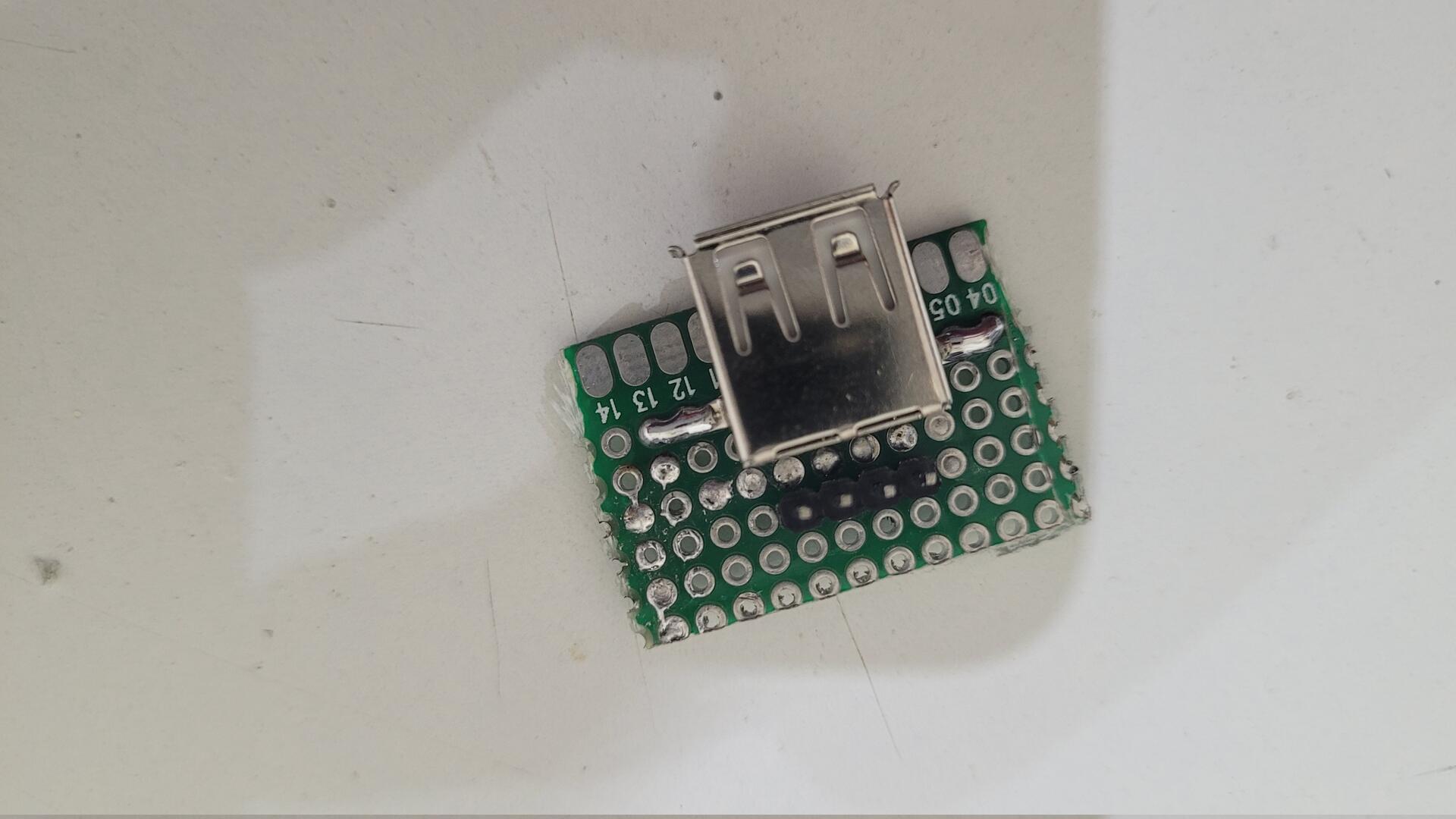
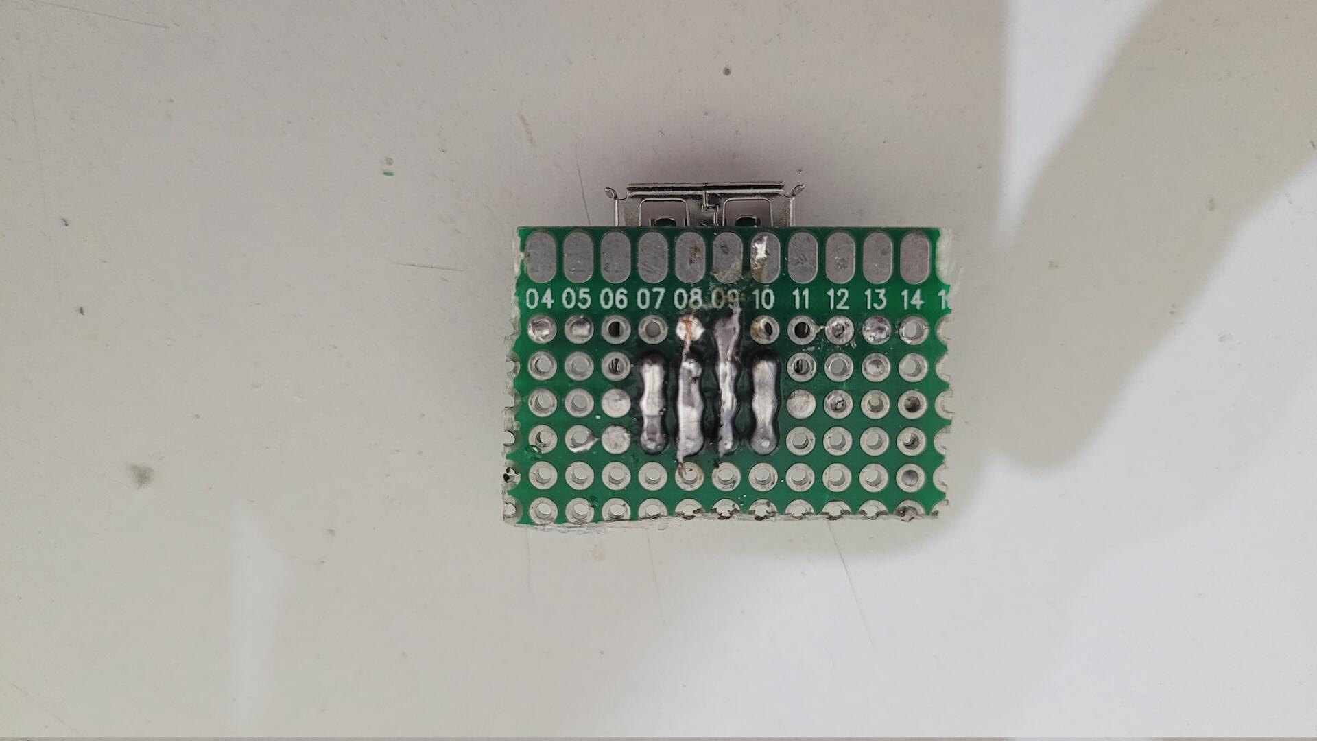
I also made a standarc USB A port mini board to wire it directly on a free USB extention on the motherboard, as there were not enough space on the back of the motherboard to use one of its USB connectors.
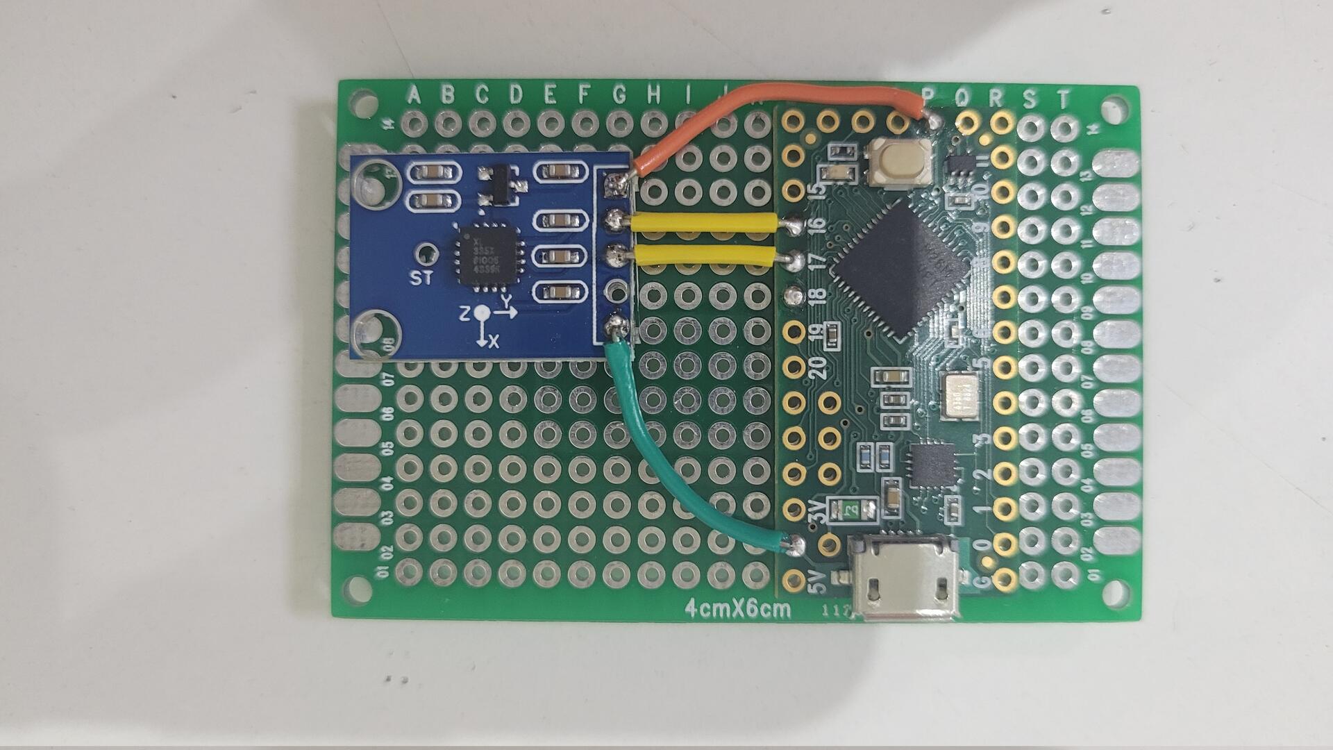
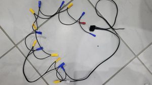
The GPIO ports of the the Teensy have been exposed on the breadboard to solder all the buttons’ wires. Each wire has a red electric pod on its end, which is directly pluggable onto any button. The ground is solderered to the Teensy and basicaly consists in a chain of blue pods

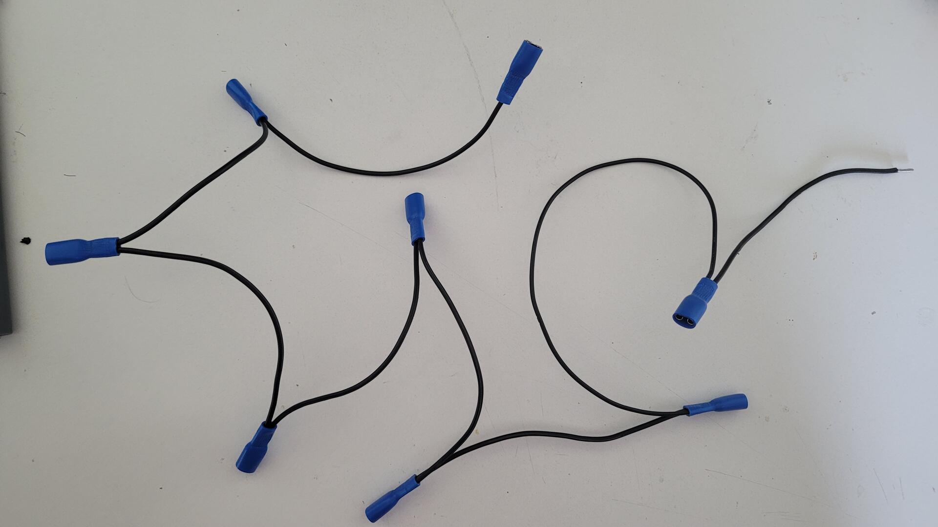
Every button is backlit with a led, which means additional wires from a 5V source. The ATX power supply provides the required current, so I used one of the power supply plug to build a chain of pods for +5V and ground.
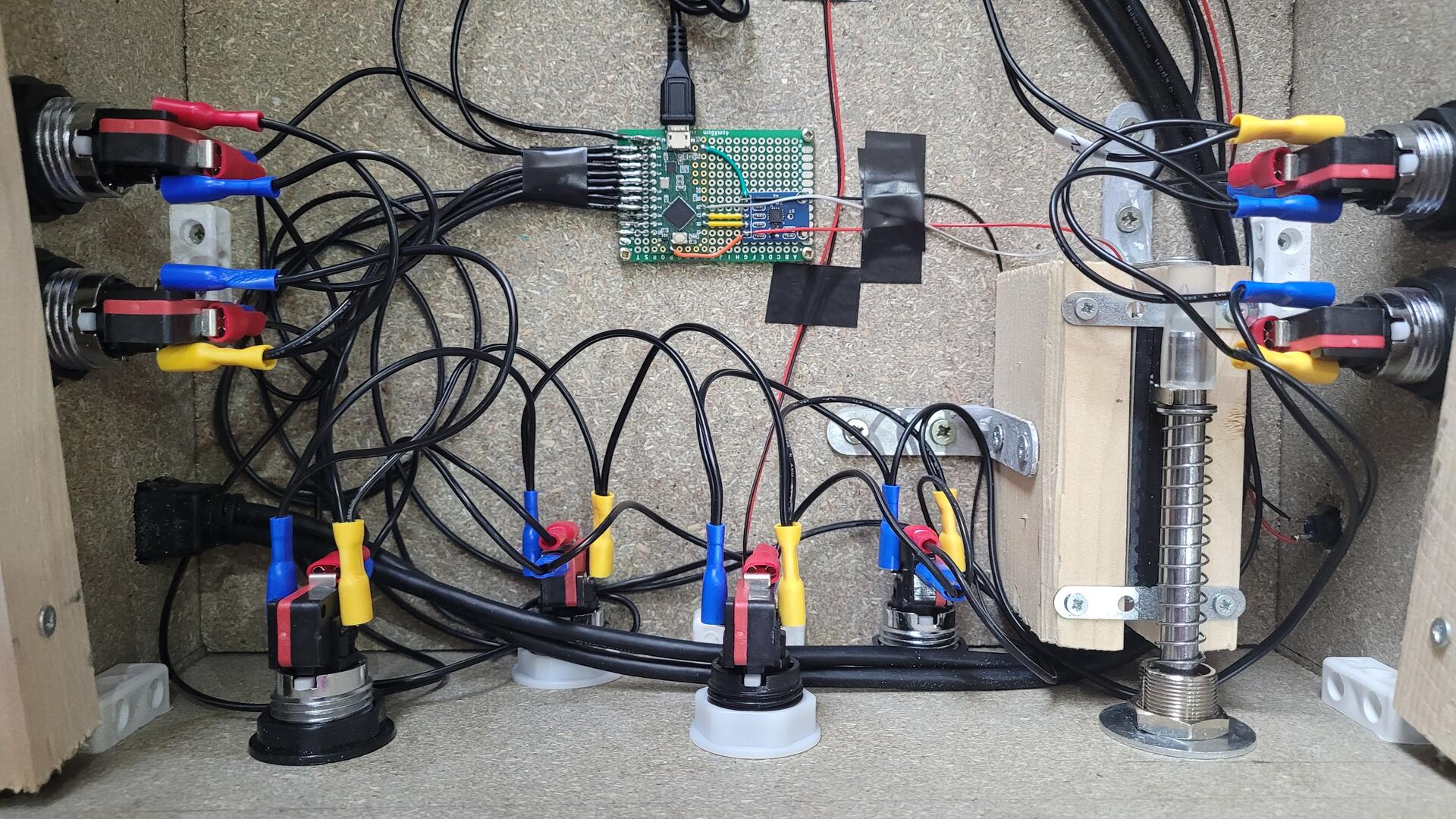
Finally, here is the “brain” fixed on the bottom of the cabinet, with the plunger’s potentiometer also soldered to one analog input of the Teensy
Below is an overview of all the controls wired…
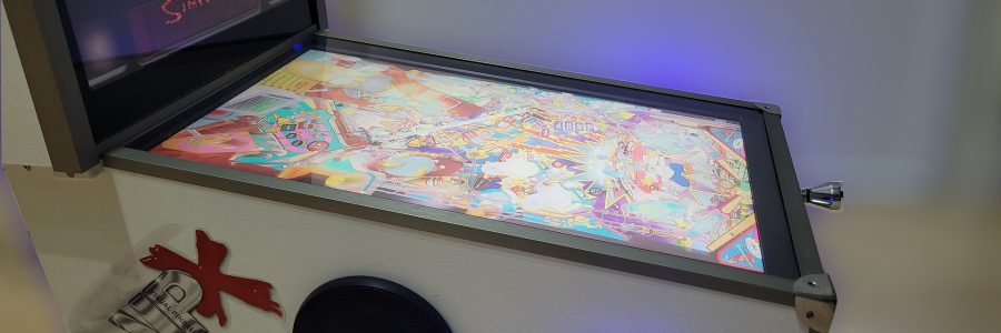
…And here an overview of the cabinet before putting the playfield screen :
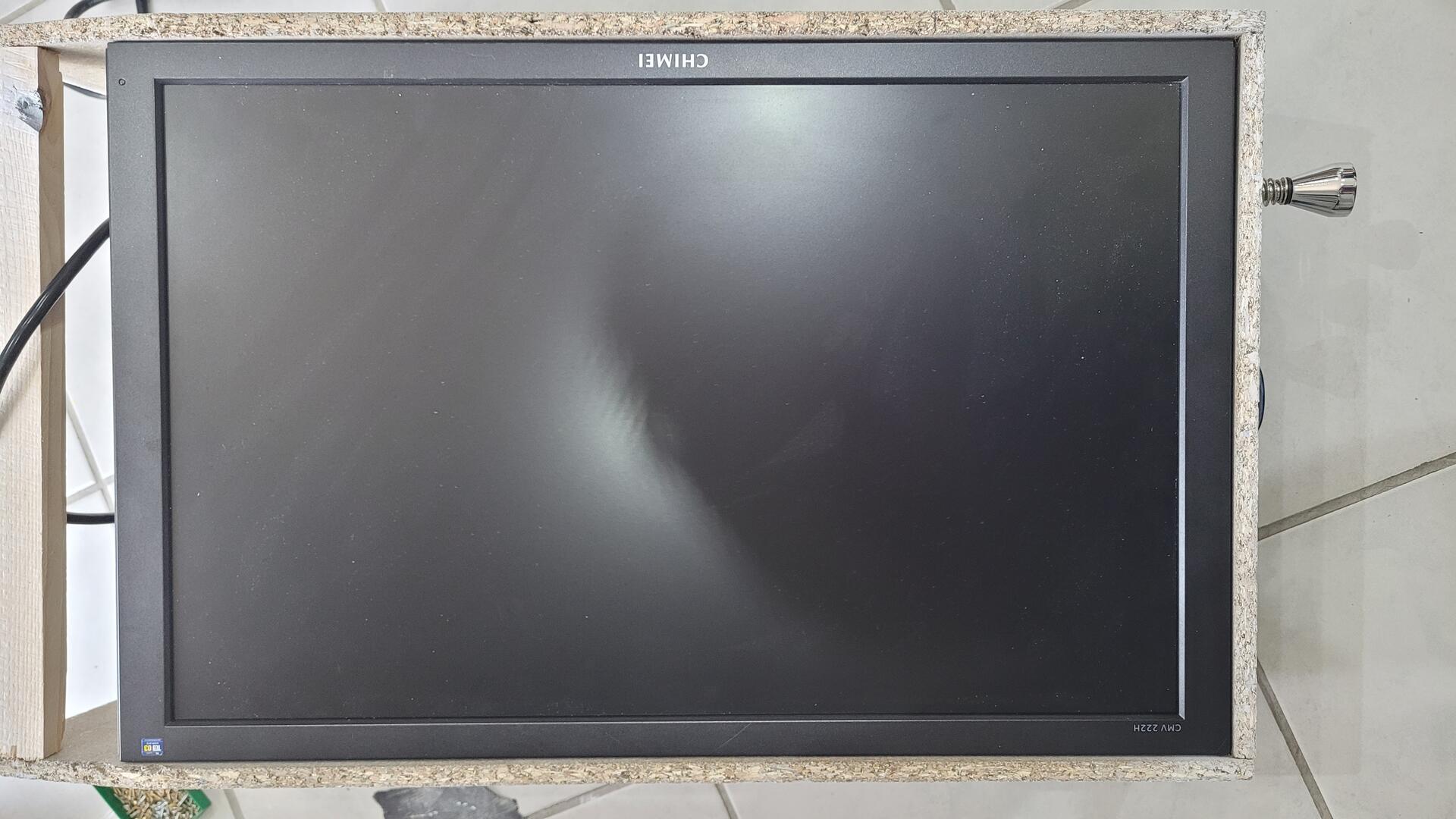
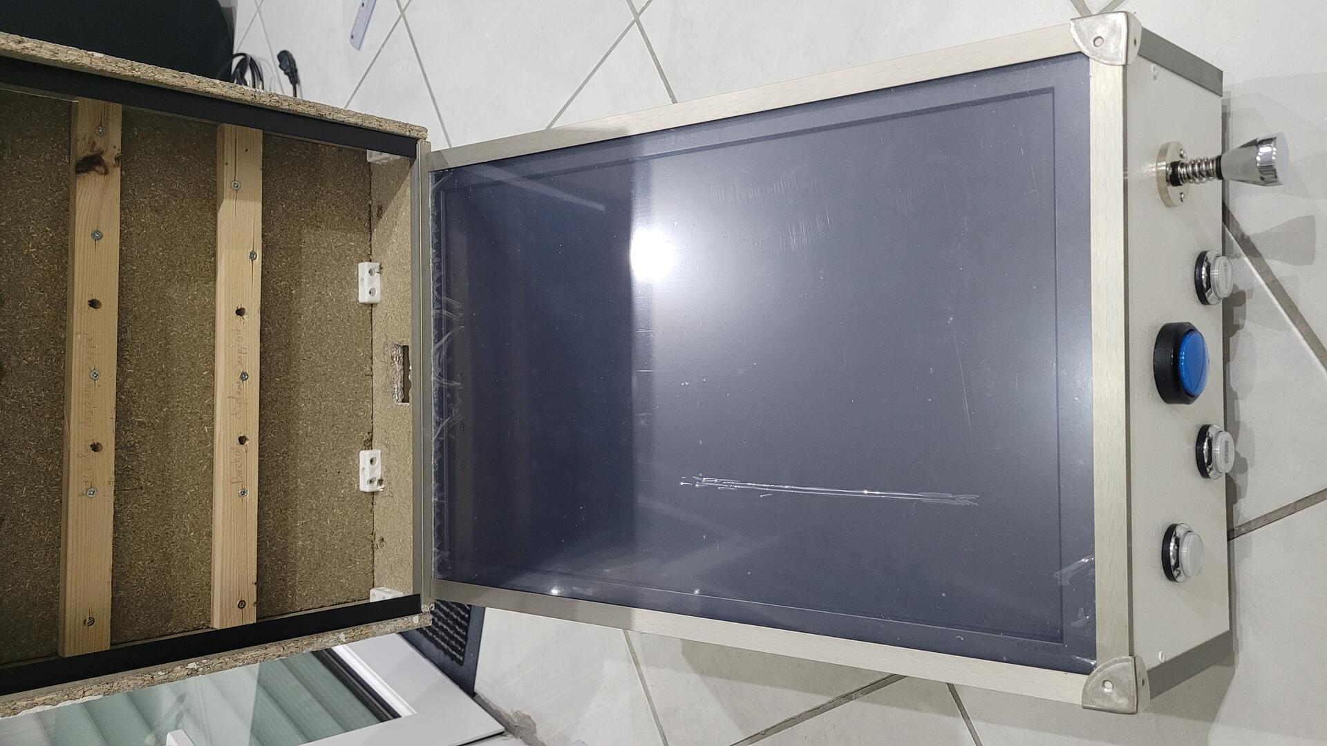
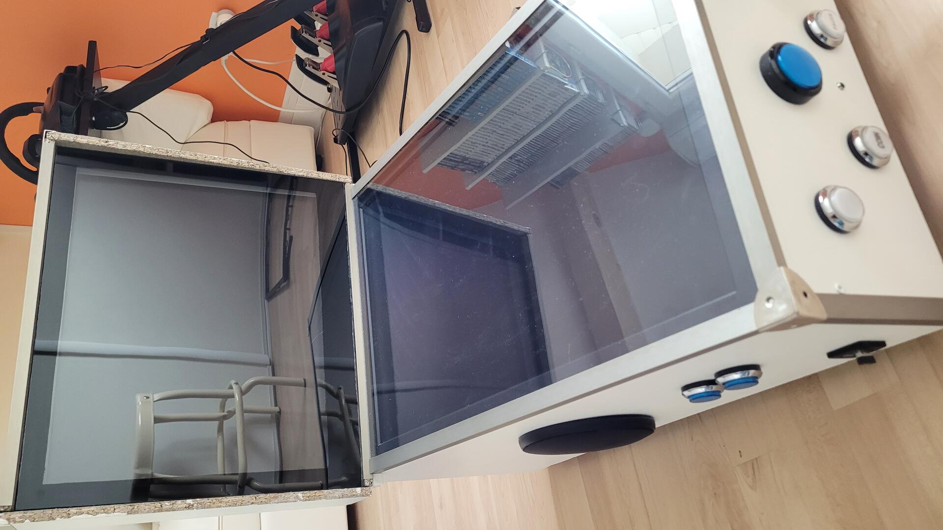
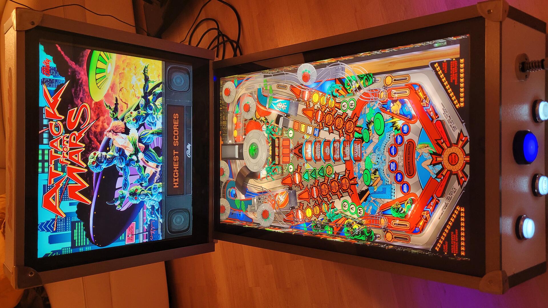
Playfield display
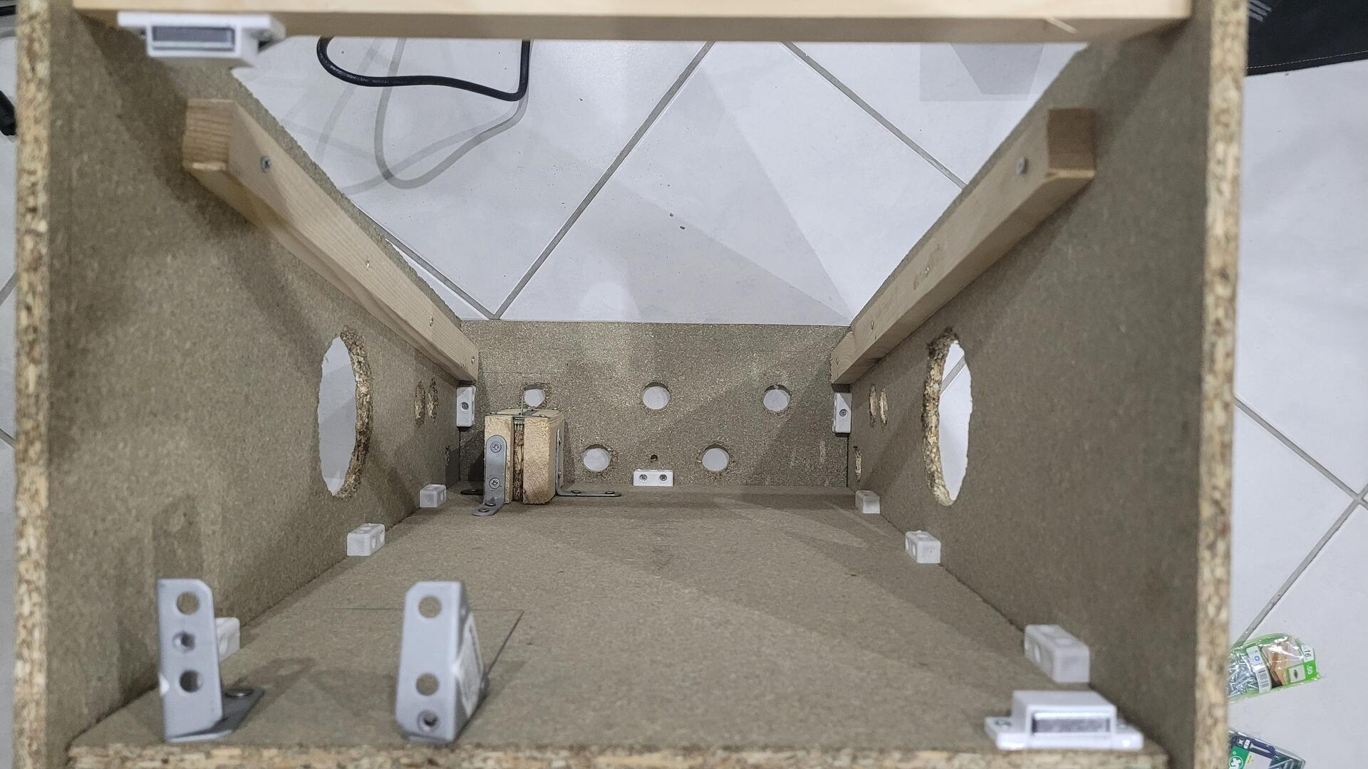
The playfield screen is inserted with just enough force to be held in place. The photo on the right show the inside of the cabined from the back, with the screen in place.
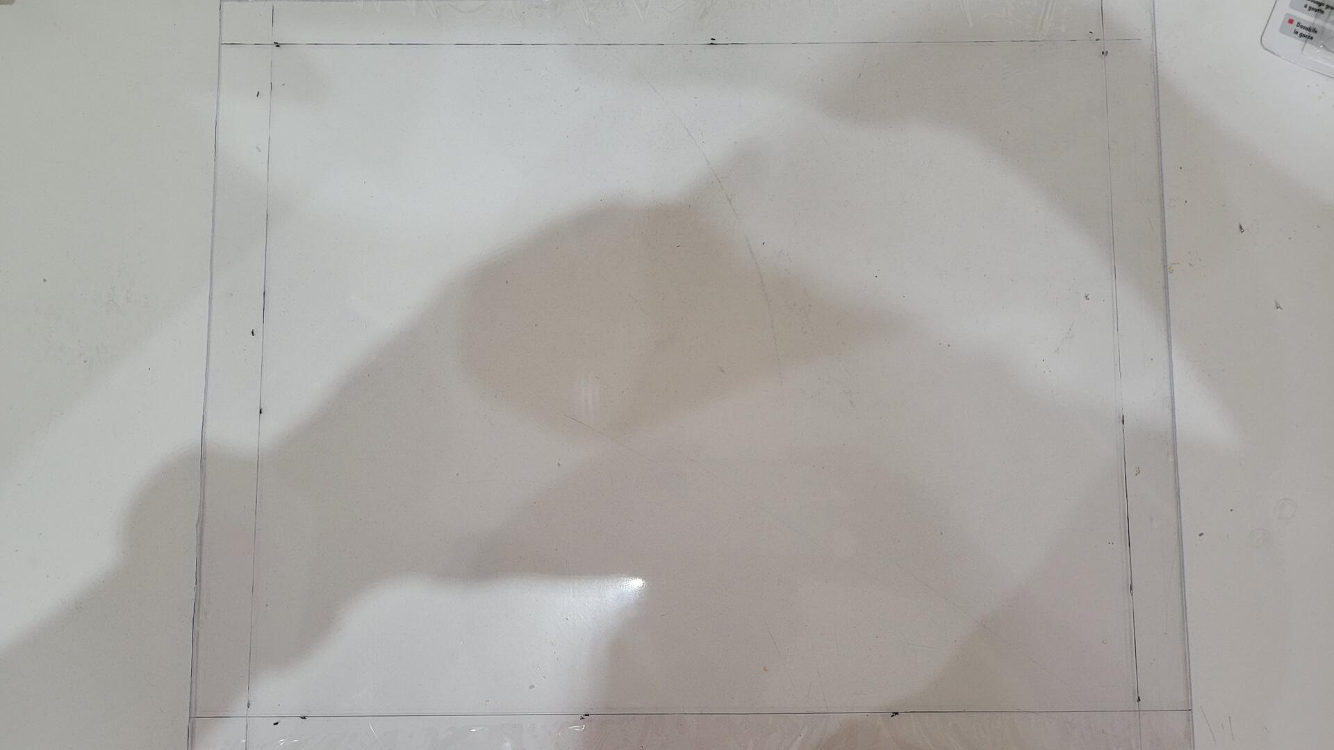
The screen is protected with a 2mm piece of plexiglass. I cut it with a cutter using a rule. After 2 or 3 passes, the plexiglass can be broken straight. The plexiglass is placed over the screen and cover all the cabinet width. It is fixed only with the edge metal bars (see below).
Backglass mounting
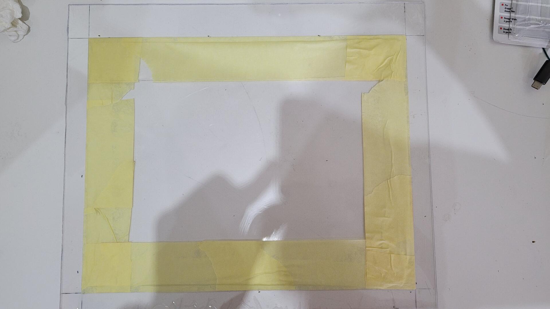
The backglass screen is also protected by a piece of plexiglass, but this time it had to be maintened vertically. I used some black plastic edges on the inside so the plexiglass can be fixed with double sided adhesive tape.
As the plexiglass is taller and wider than the effective display surface of the screen, I painted the “margins” with black spray paint. The plexiglass being protected by a thin plastic film, I removed it only on the parts to be painted. I added some adhesive to ensure a good protection before painting.
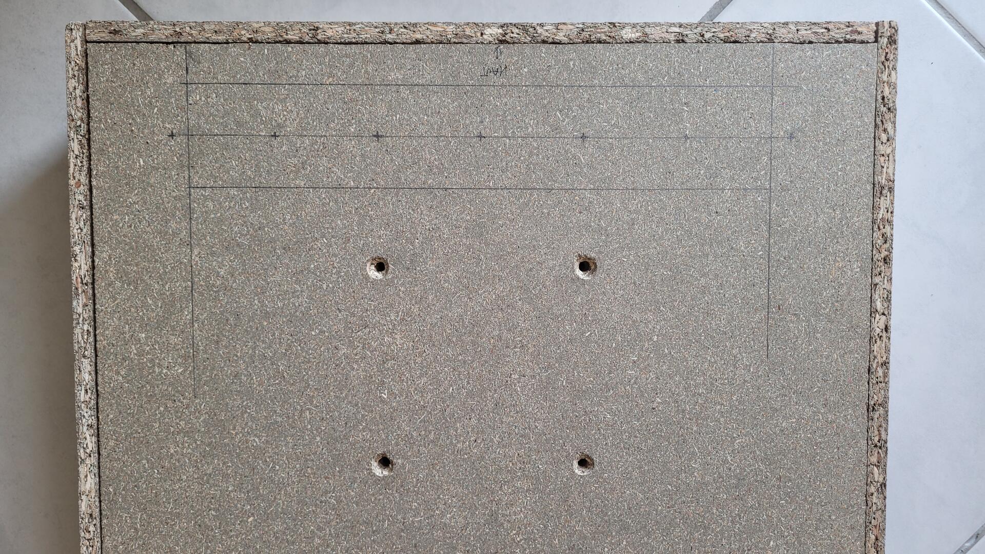
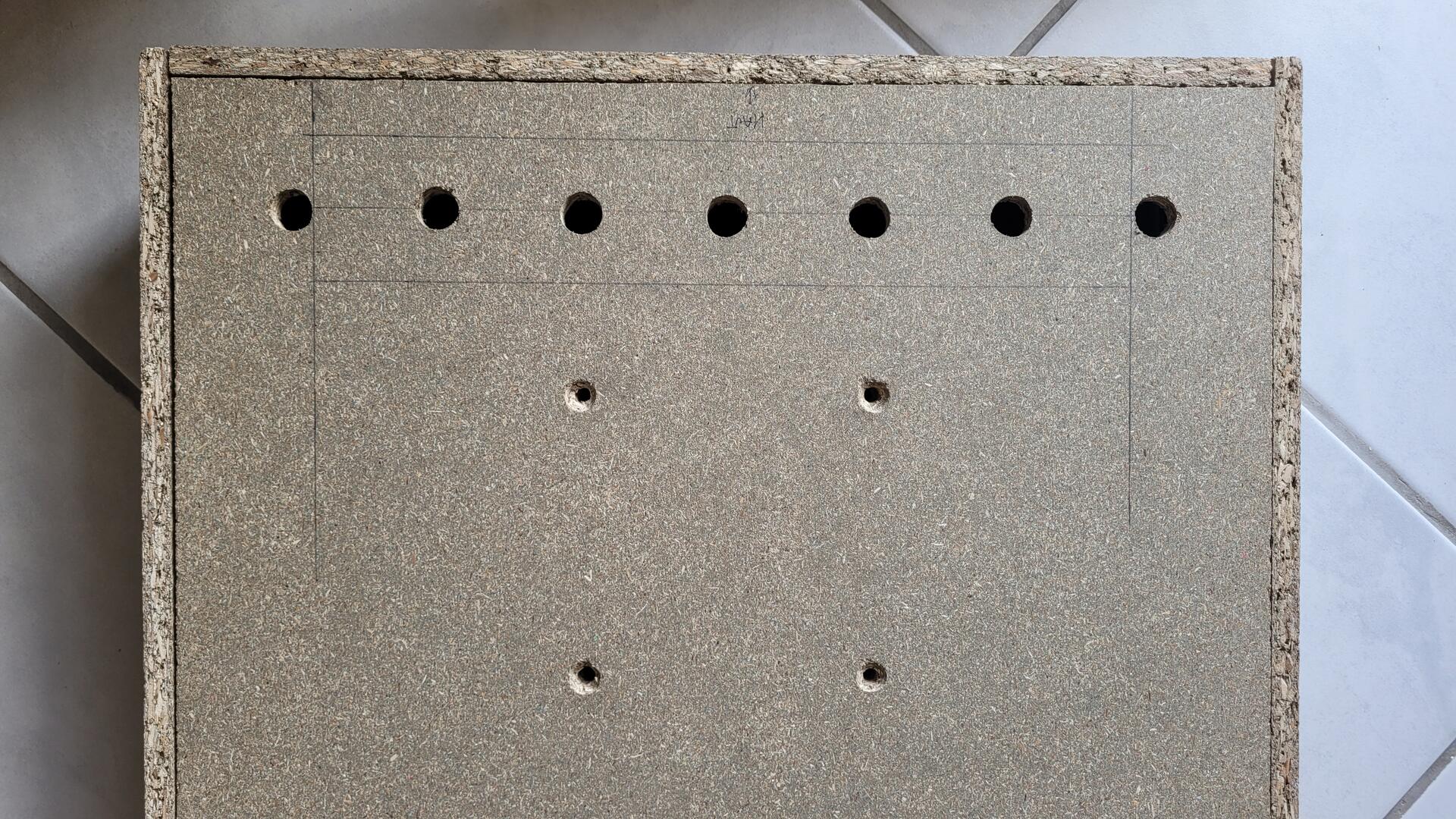
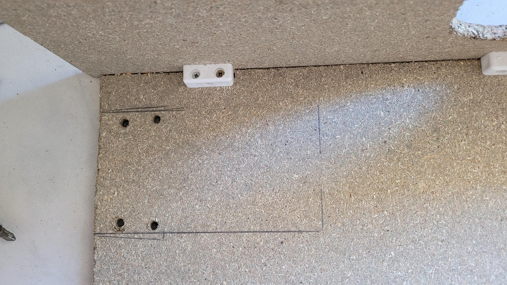
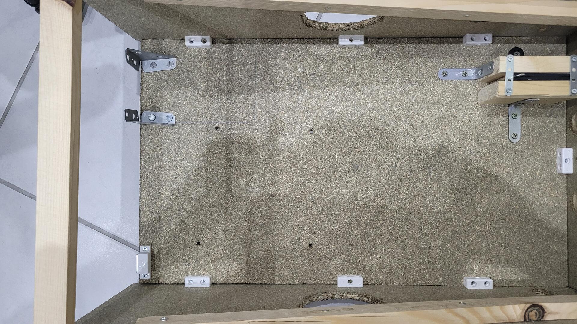
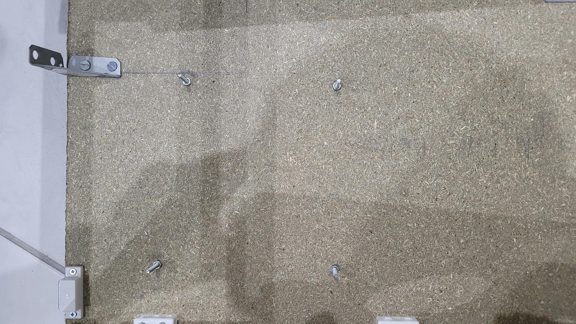
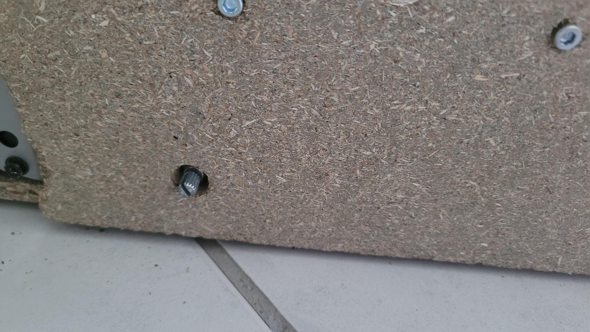
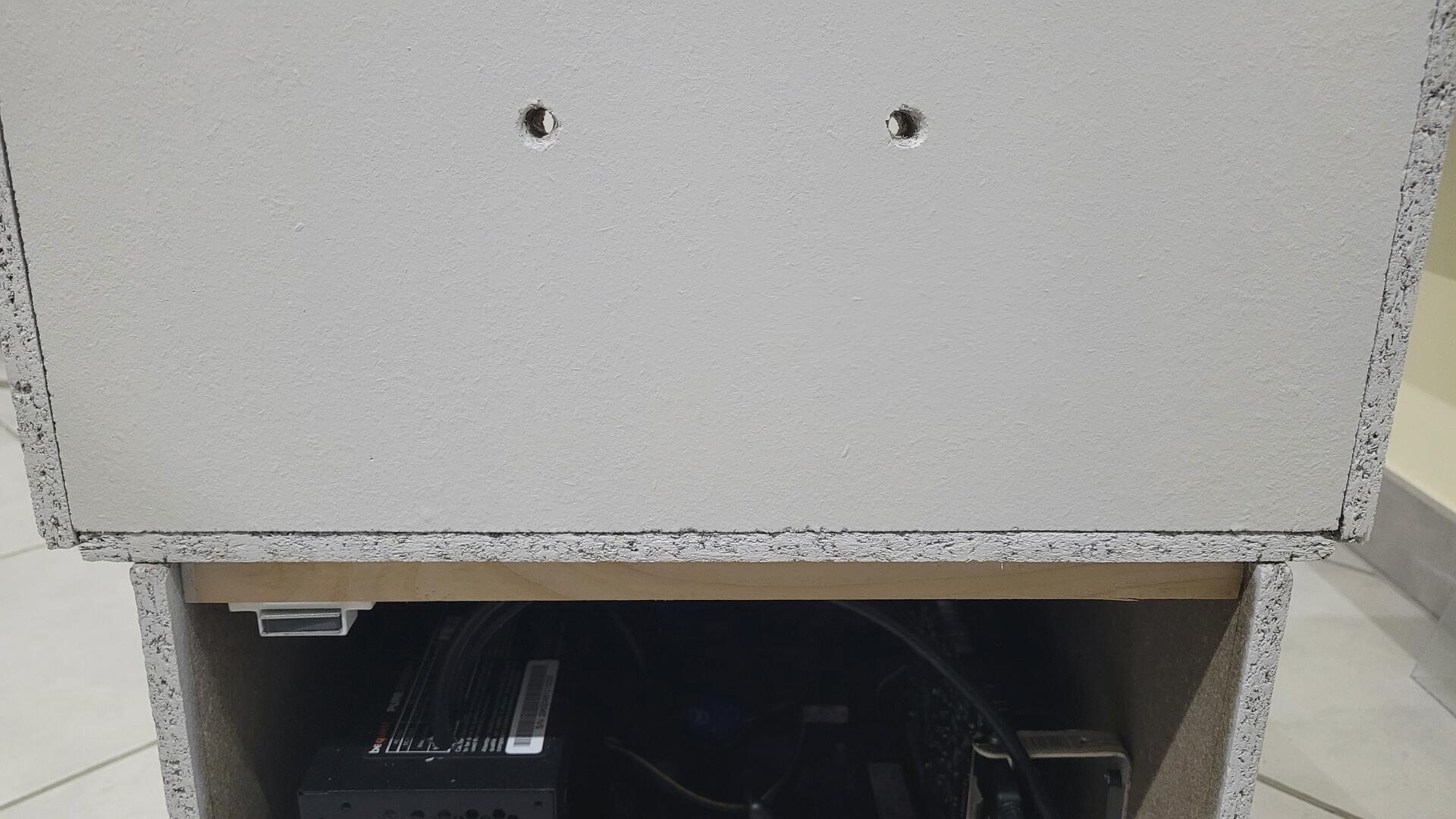
The backglass part of the cabinet is screwed from the bottom with screws and bolts. Below are the holes I made for this purpose
And here is the backglass part fixed to the cabinet
Edge and corner finish
The original edges and corners of chipboard wood are not really nice. In order to get a more polished / industrial finish, I glued some piece of brushed aluminium on all egdes. For the playfield, I let just enought space to be able to slide the plexiglass.
For the corners, I used some metal “protections”, I guess they are normally used to protect and / or assemble furtinure corners.
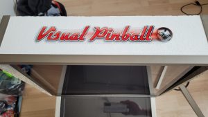
Decoration Stickers
I know that “simple is beautiful”, but it’s not enought “arcade” :). I wanted to put a small touch of color on the cabinet. Basicaly I took some picture from the internet, and printed them on a transparents adhesive paper with an inkjet printer.
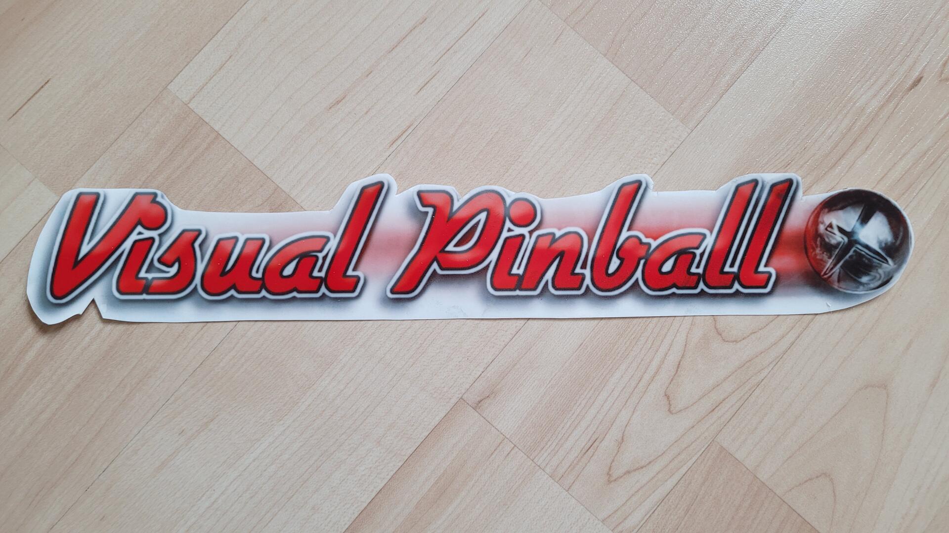
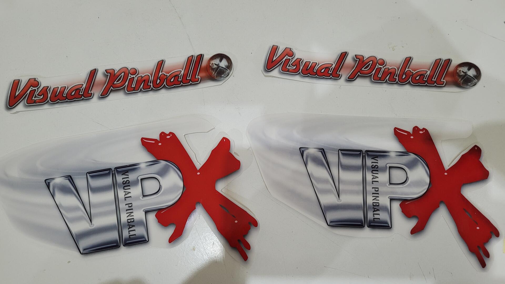
I put the décoration on the top of the backglass and on each side
Software part
Preparing Windows 10 (pro)
By default Windows 10 comes with a lots of features that could be either disturbing or cause slower booting for a dedicated gaming machine like a visual pinball cab.
Here is what I did on mine :
- Disabled “news and interest”
- Uninstalled all possible applications from stock install
- Lock screen settings : Turned off lock screen background picture and “fun facts, tips and more”
- In the task bar settings : set to automatically hide, and use “small taskbar”
- In the theme settings : I disabled all standard desktop icons from “Desktop icon settings”
Some services can also be stopped (command line):
|
1 2 3 4 5 6 7 8 9 10 11 12 13 14 15 16 |
sc config "stisvc" start=disabled sc config "iphlpsvc" start=disabled sc config "lmhosts" start=disabled sc config "SCardSvr" start=disabled sc config "DiagTrack" start=disabled sc config "RasMan" startdisabled sc config "BthAvctpSvc" start=disabled sc config "diagnosticshub.standardcollector.service" start=disabled sc config "WbioSrvc" start=disabled sc config "PcaSvc" start=disabled sc config "NetTcpPortSharing" start=disabled sc config "bthserv" start=disabled sc config "DPS" start=disabled sc config "TabletInputService" start=disabled sc config "Spooler" start=disabled sc config "WSearch" start=disabled |
Finaly I followed the official documentation for autologon : https://docs.microsoft.com/en-us/sysinternals/downloads/autologon
Teensy LC HID sketch
Using the Teensy as a standard USB joypad is pretty easy with the included “joystick” library that comes with the IDE. They are plenty of exemples on the internet, below is my code :
|
1 2 3 4 5 6 7 8 9 10 11 12 13 14 15 16 17 18 19 20 21 22 23 24 25 26 27 28 29 30 31 32 33 34 35 36 37 38 39 40 41 42 43 |
const int numButtons = 8; // left pin x2, right pin x2, start, coin, pause, exit byte allButtons[numButtons]; void setup() { Serial.begin(9600); Serial.println("init controler..."); Joystick.useManualSend(true); for (int i=0; i<numButtons; i++) { pinMode(i, INPUT_PULLUP); } Joystick.X(512); // init nudge X (tilt) Joystick.Y(512); // init nudge Y (tilt) Joystick.Z(512); // init plunger // neutral dpad as is not used and should not disturb key dectection during settings Joystick.hat(-1); } void loop() { // nudge Joystick.X(analogRead(2)); Joystick.Y(analogRead(3)); // plunger Joystick.Z(analogRead(4)); // read digital pins and use them for the buttons : 1 = not pressed, 0 = pressed for (int i=0; i<numButtons; i++) { if (digitalRead(i)) { allButtons[i] = 0; } else { allButtons[i] = 1; } Joystick.button(i + 1, allButtons[i]); } Joystick.send_now(); // runs 200 times per second delay(5); } |
Visual Pinball softwares
There are tons of documentations on the internet, so I just give here some things specific to my build.
Main engine and Frontend
To make it simple, I chose to only use one engine : Visual Pinball X (VPX). It has a lot of tables, at least enough for me.
For the Frontend, I used pinballX which I found simple to use and to configure. It even allows to generate video previews of the tables you installed !
Here is the guide I followed : https://www.vpforums.org/index.php?app=tutorials&article=160
If you are discovering the world of visual pinball, a full table consists of :
- A “.vpx” file which defines the table that Visual Pinball X runs
- A “.direct2bs” file which provides the backglass display material
- Eventualy, a PinMame rom to drive the DMG display and the game’s logic
Graphics settings
Regarding the hardware described in the begining of this post, here are the main settings I used:
- In vpx : set to “high end PC”
- In the nvidia control panel : power management mode is set at “prefer maximum performance” and “Low latency mode” is set to on
With the “Flingston” table, I get between 110 and 180 fps without V-Sync, so a constant 60fps with V-Sync and a cool gfx card.
Also, my playfield screen being “small” and with a 16:10 ratio instead of 16:9, I zoomed all the tables to maximize display size without compromising the gameplay.
Some TIPS
As I found some issues during my build, I decided to share them together with the solutions :
- if the directB2S backglass does not appear: make sure you selected the right screen in B2S_Setup, and check that your “.directb2s” files have the same name as the table file
- if the DMD display does not appear for pinball with no pinmame rom : check that “enabled=true” is present in VPinMAME\DmdDevice.ini
- If you have lot of audio noise with the analog stereo out : set audio to AC97 instead of HD Audio in the BIOS
- “Pause” is not really possible with VPX. You can map exit button that actually pauses the game, but if you want direct exit, it will quit directly
- You can add “-exit” in as argument for VPX start command, so you can exit directly by pressing the exit button (no menu)
- You may want a “open door” button to access some pinball settings. I mapped it to one button on the front. I used others existing buttons to map up, cancel and enter (do not map them to “exit” or “left”/”right” pinball)
- You can use “-extminimized” argument for VPX command to start it minimized from pinball X
Results
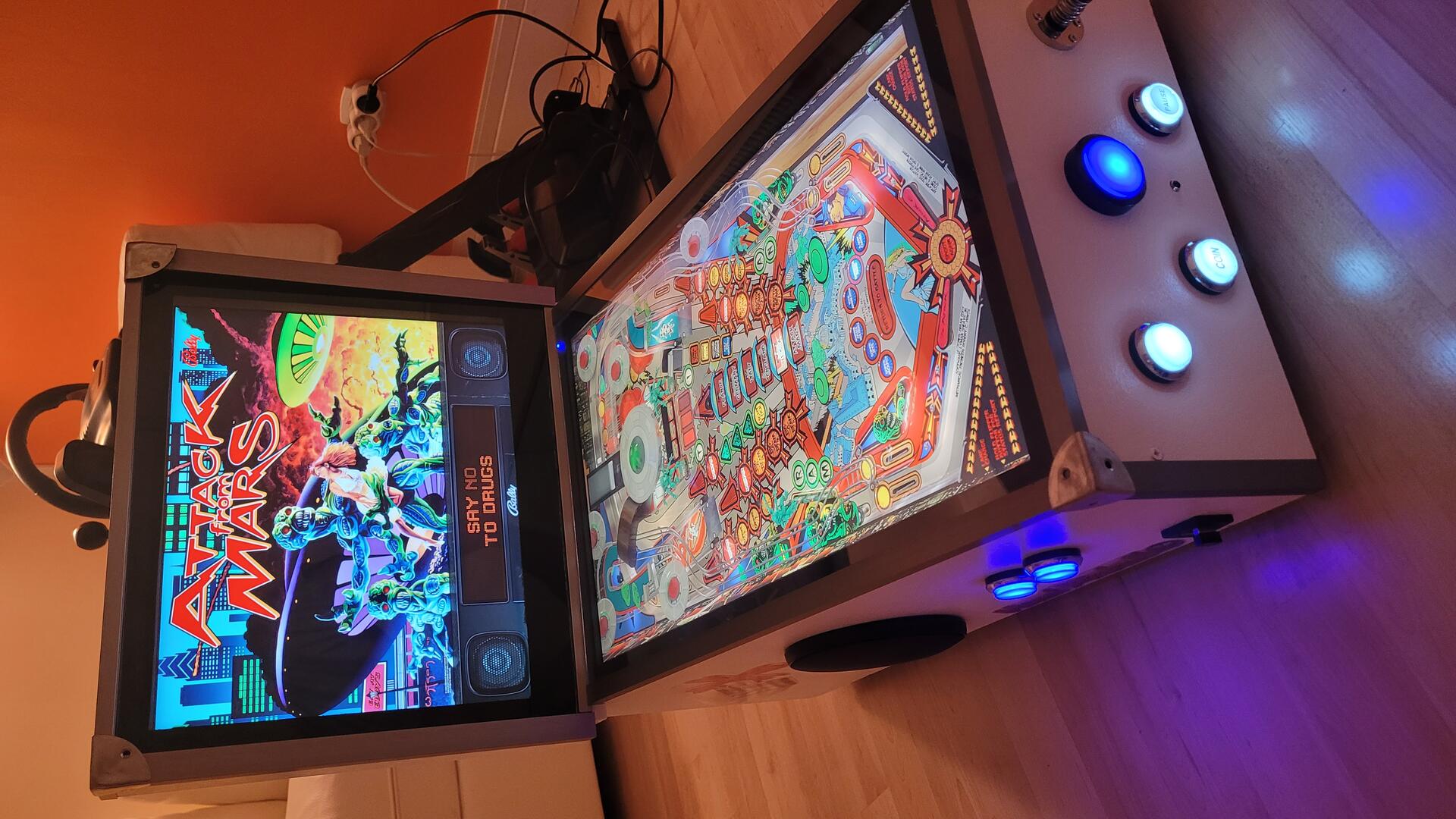
Nice tutorial! thank you