Odrophile : odroid C0 based audiophile tablet
The Odroid C0 is definitly one of my favourites DIY plateform : RTC, lipo support, emmc, fast cpu / gpu and low power consumption ! This time, I made an “audiophile” tablet with a neo-retro look, based on a C0 and the Hifi shield plus.
Features
Hardware
- 7 inch capacitive touch display
- High quality I2S DAC
- Audio out : mini stereo jack, RCA and Toslink
- Led vu-meter with 7 level for each chanel
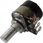
- Rotary potentiometer used to switch on/off the tablet and control the volume
- The rotary potentiometer is also touch sensitive
- 6000 mah lipo battery
- battery meter
- 1x USB 2.0 port
- 1x micro usb port for charging
- 2x ps3 copper pad

Software
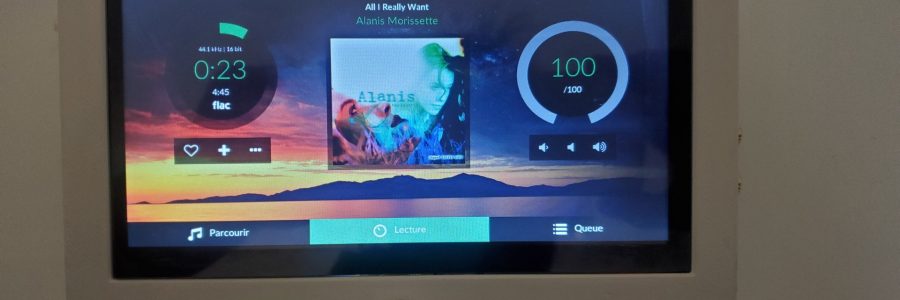
The tablet runs a slightly tuned Volumio image to make it boots faster and to manage specific functionalities such as the touch sensitive potentiometer, vu-meter and battery monitor.
Used components
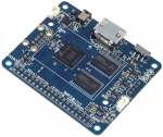
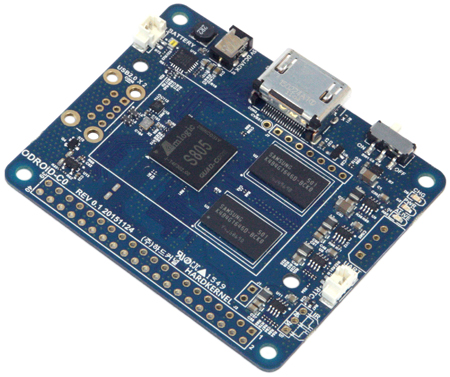
- Odroid C0
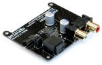
- Hifi shield plus
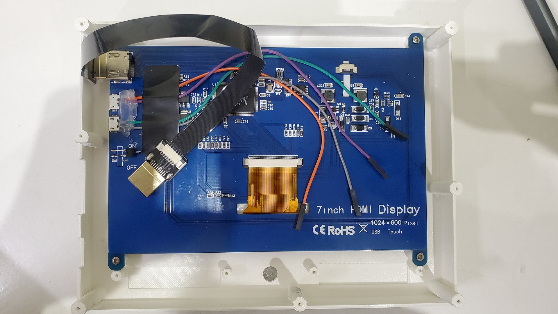
- Generic 7inch HDMI touchscreen
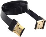
- HDMI fpv cable with one 90 degree connector
- No-name Lipo battery from ebay (model ref 906090 on ebay)
- 2x breadboards (4cm x 6cm)
- 14x 3mm leds (8 green, 4 yellow, 2 red)
- 1x female USB connector
- 1x micro usb breakout
- 1x CR2032 battery holder
- 1x rotary potentiometer with on / off switch (with a button)
- 1x capacitive touch breakout with pad pin
- 1x stereo jack (3.5″)
- 1x stereo jack female connector
- Some dupont cables
- 6bit Multicolor LED breadboard
- Some resistors (8x 1k, 4x 4.7k, 2x 10k. 1x 1M)
- Some pin rails


Hardware build
My goal was to build something which I could repair in time, or change some parts in case of failure. That’s why I used pin rails and dupont cables instead of direct soldering.
Odroid preparation
The Odroid C0 is nude by default : no connector, no pin rail. This allows to easily arrange connectors as you want.
I started to put 90 degrees pin rails for usb ports and j7 headers as well as a standard 40 pins rails on the GPIO port:
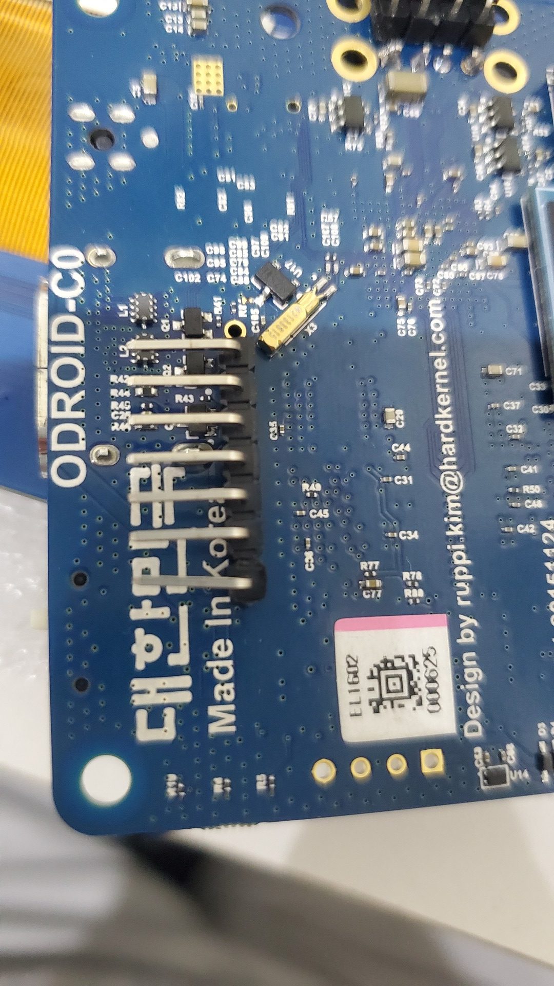
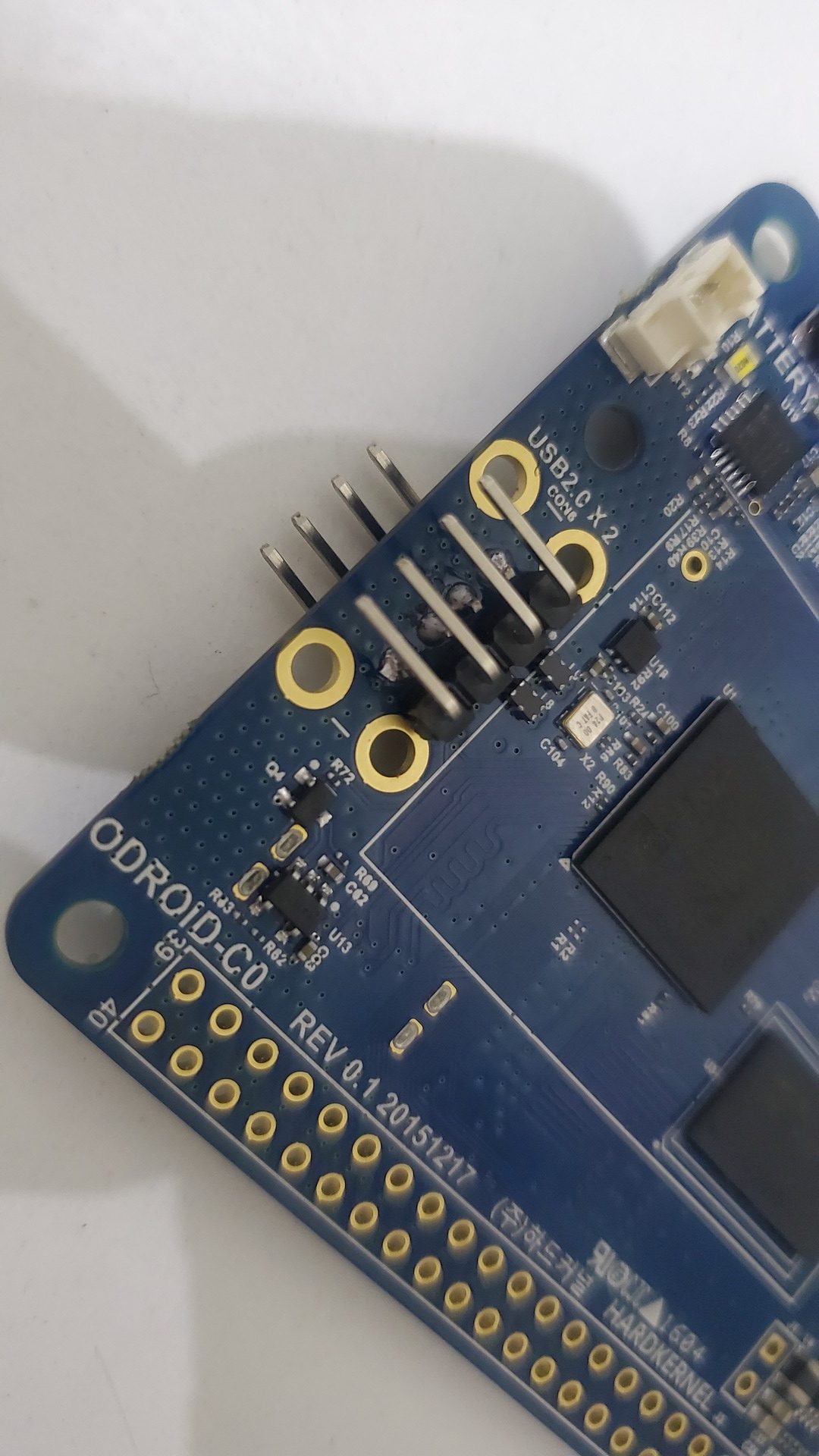
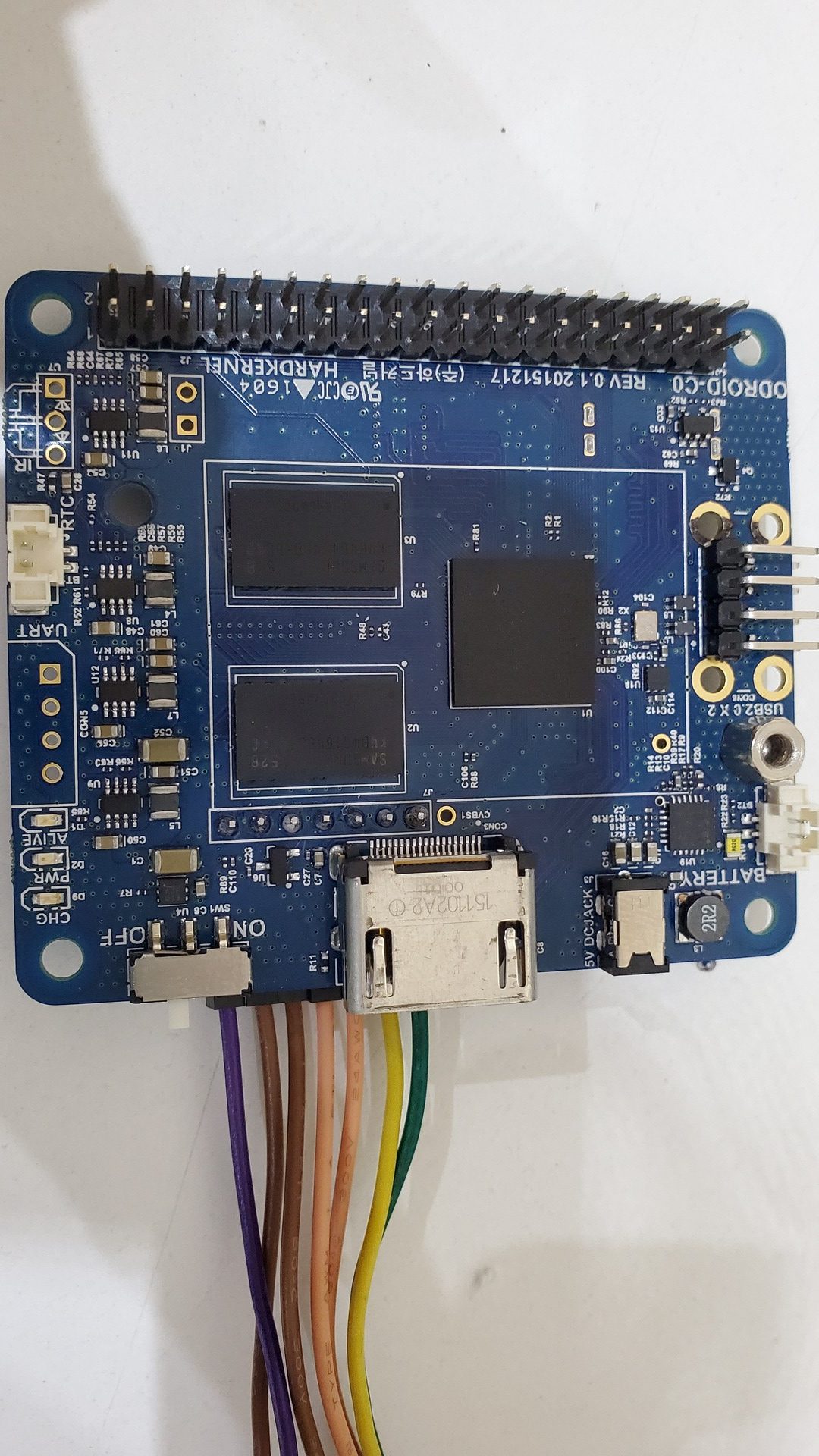
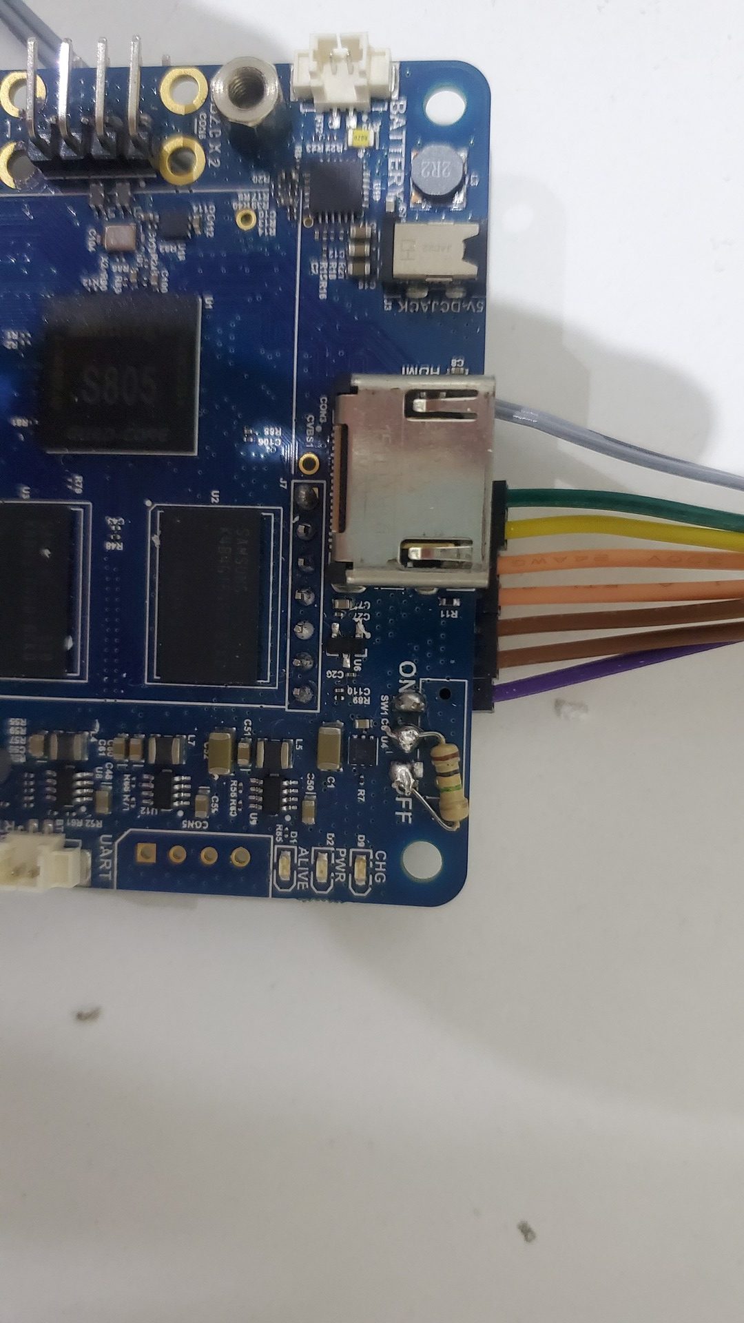
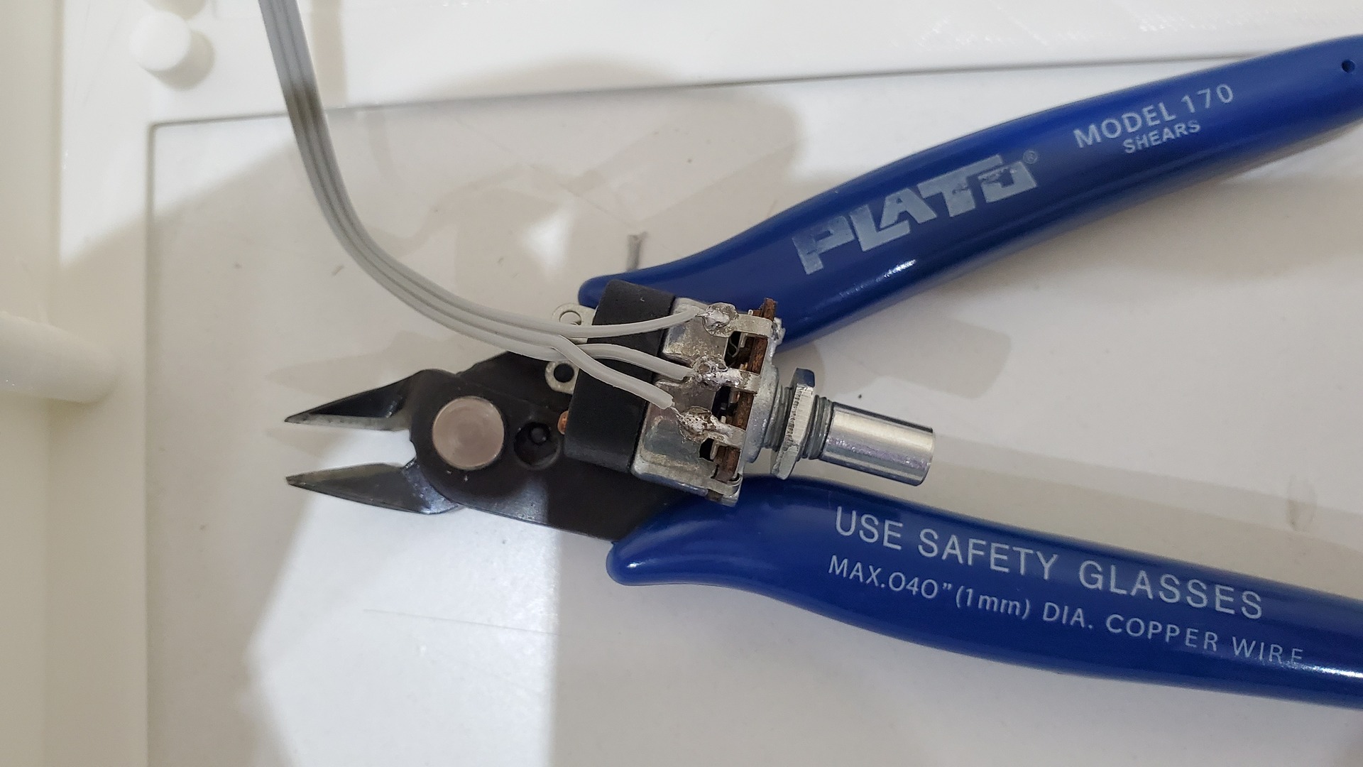
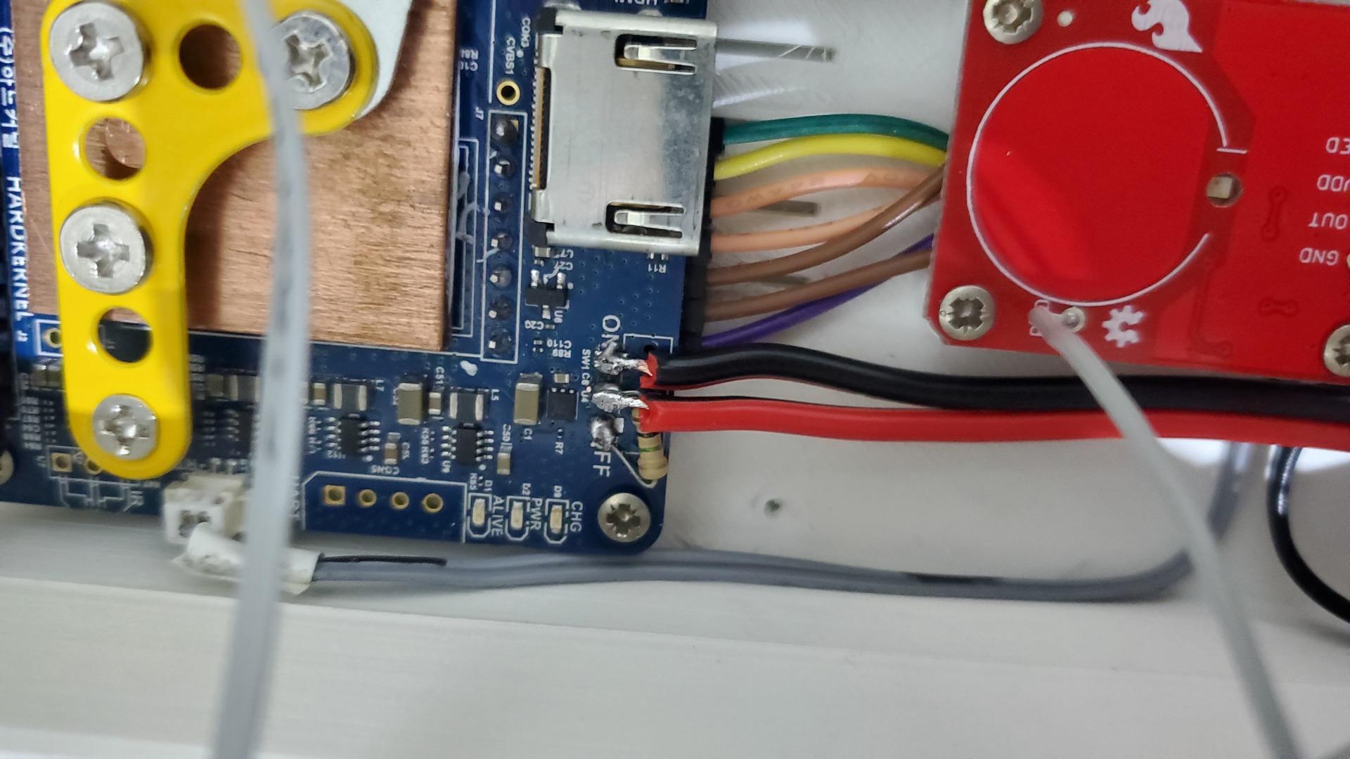
I removed the on/off switch to wire the volume knob that also have a on/off switch. Note the 1 M ohm resistor so the odroid can be switched on / off with a simple 2 wires switch (thanks to Odroid support : https://forum.odroid.com/viewtopic.php?f=111&t=39899):
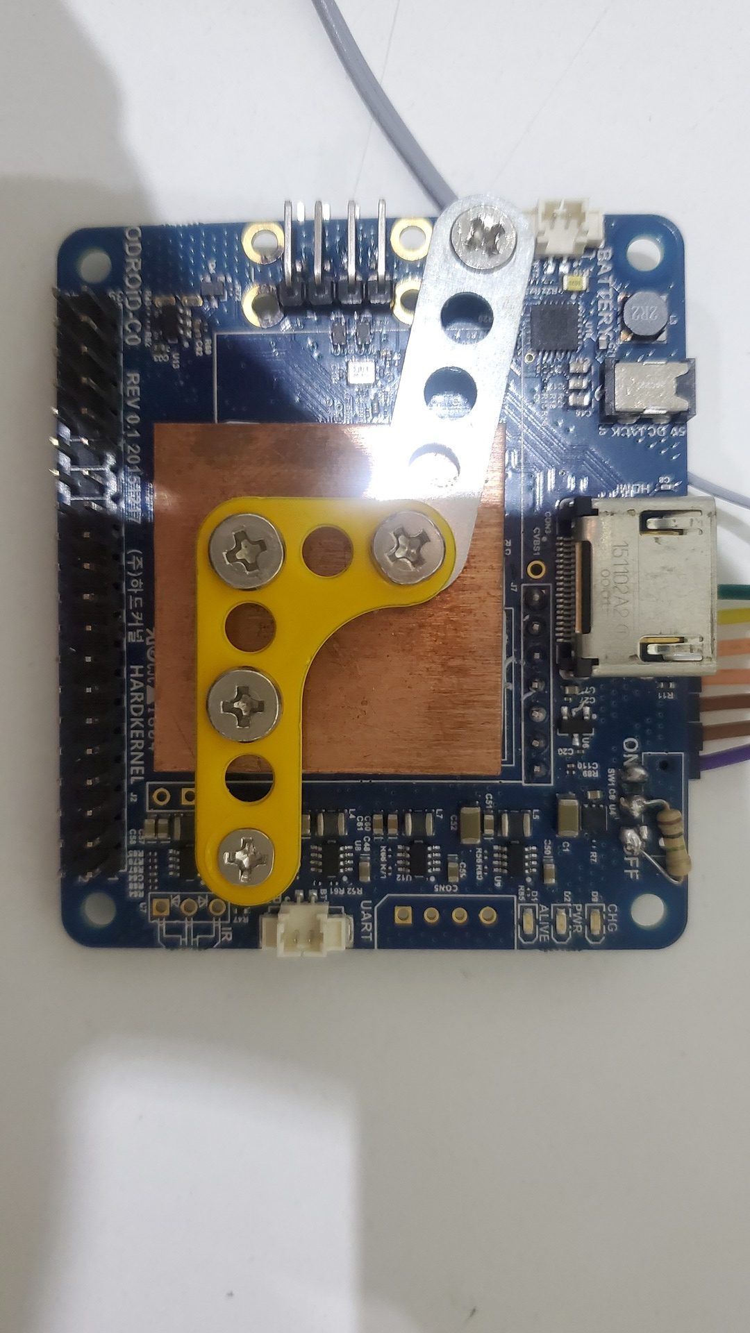
Finally, I also twisted a little bit the hifi shield connector and added the 2 copper pads with some thermal paste (fixed with meccano parts):
Display
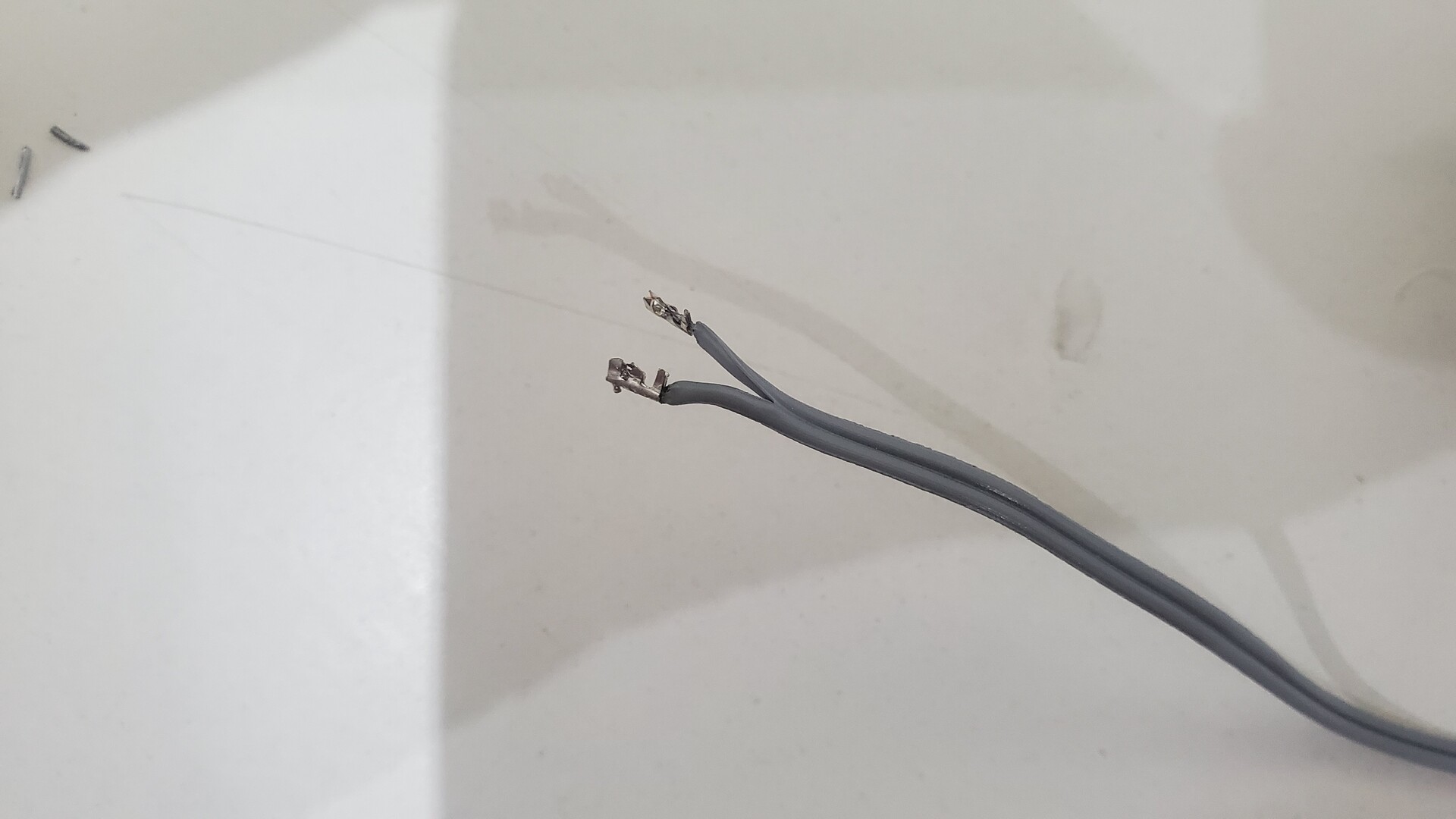
The display has two micro-usb ports, but there are linked on the same tracks. As theses connectors are very small to solder wires on it, I took +5v and D- on the upper connector and the D+ and GND on the lower connector. I used dupont cable to be able to connect the display to the usb port pins shown previously:
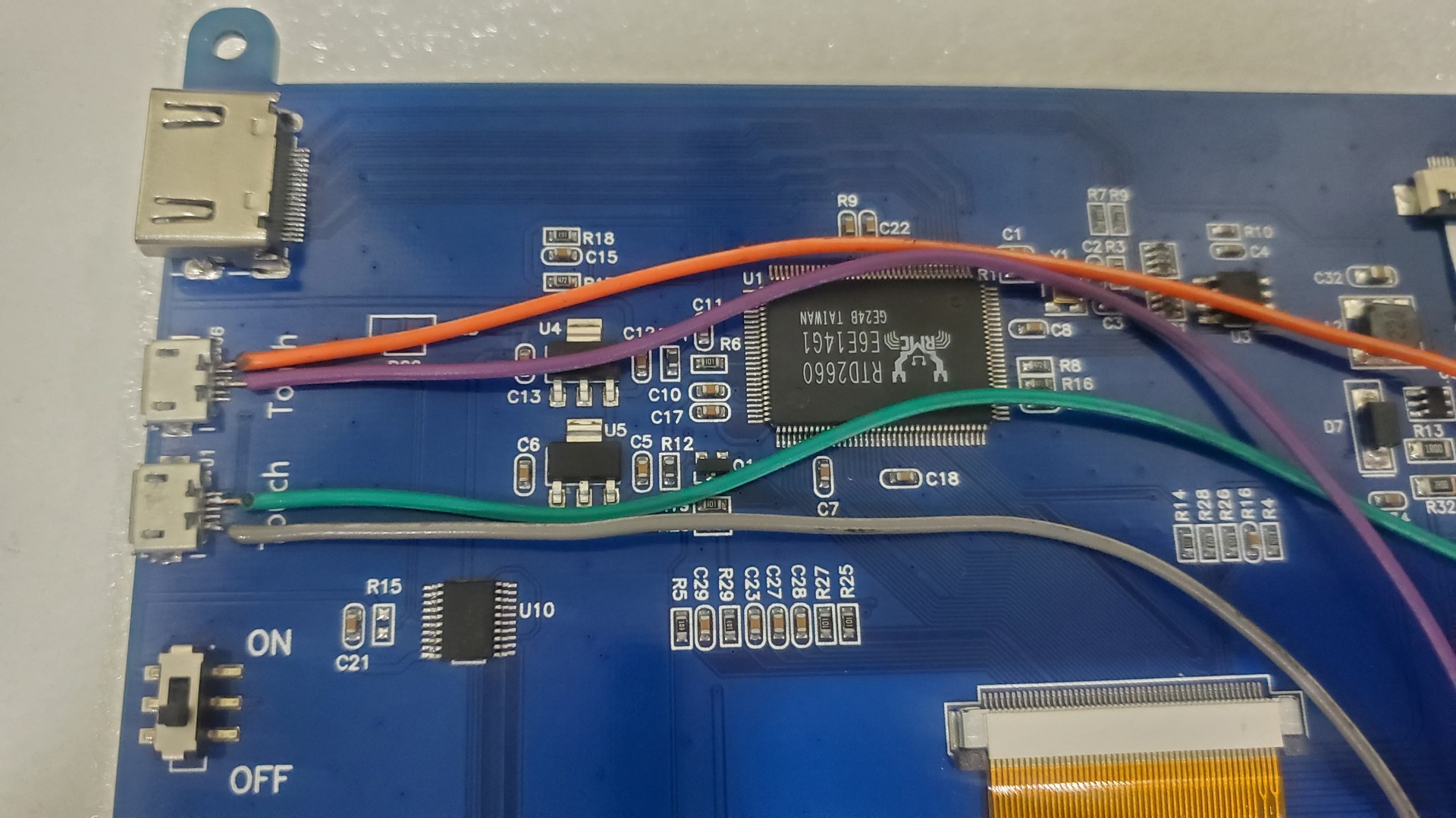
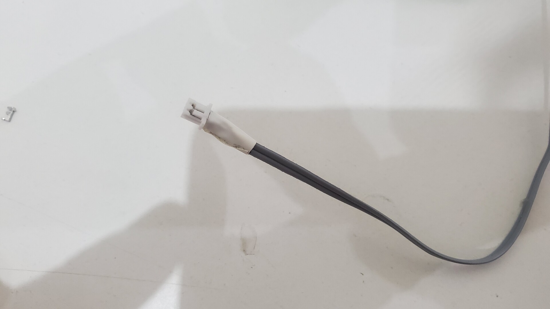
In order to securise the connection I put some hot glue and a piece of adhesive tape:

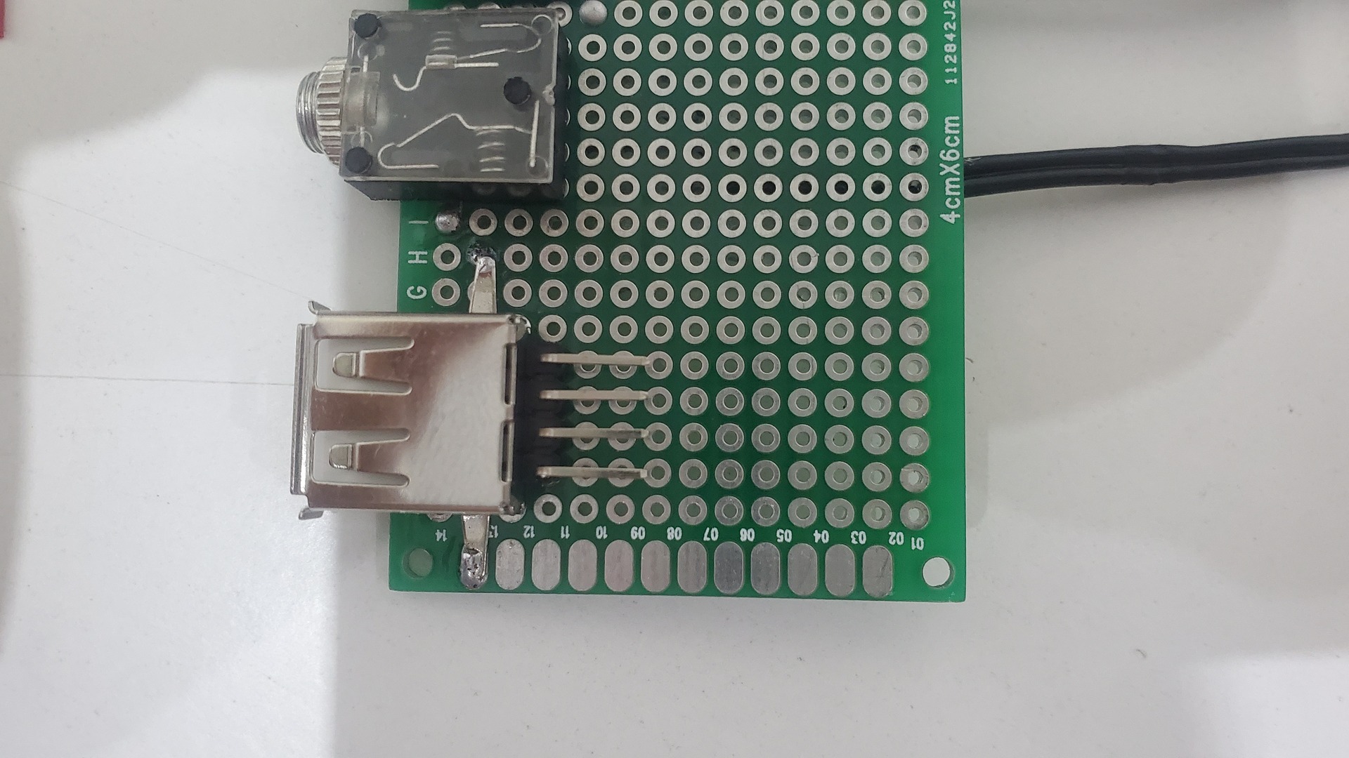
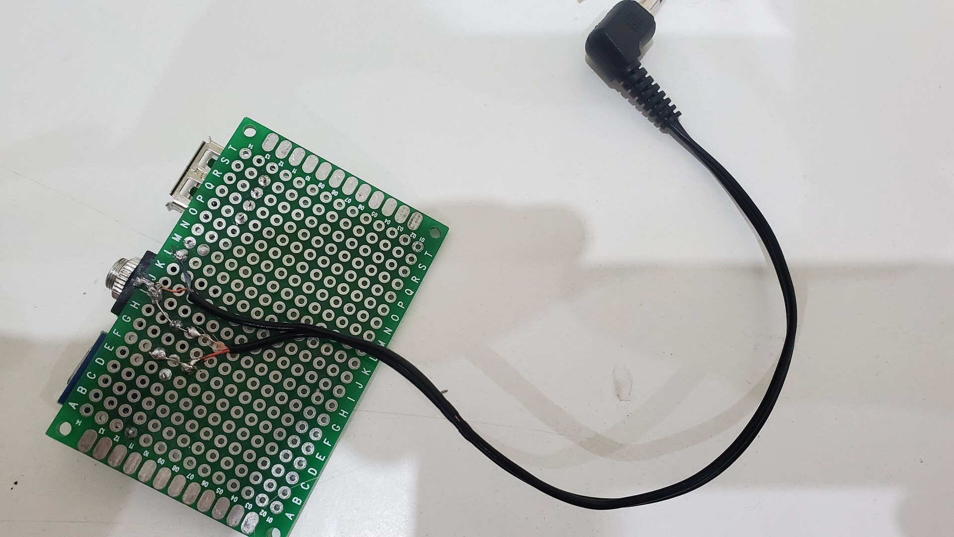
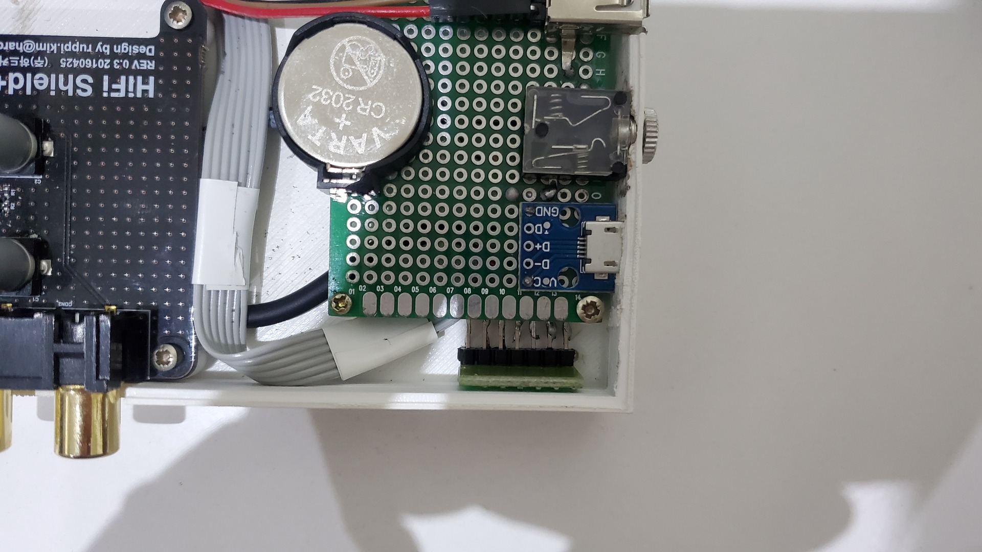
Connectors
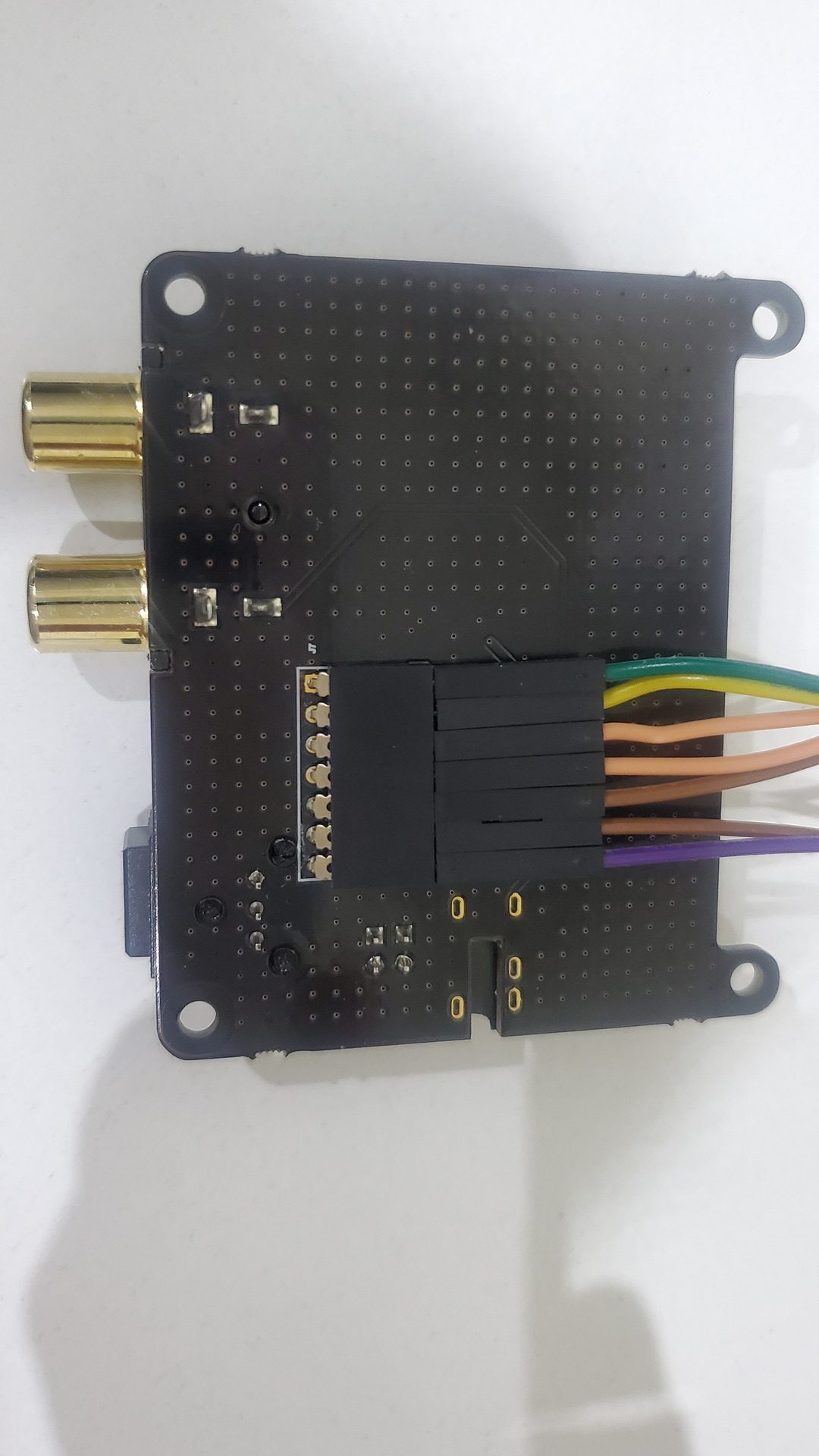
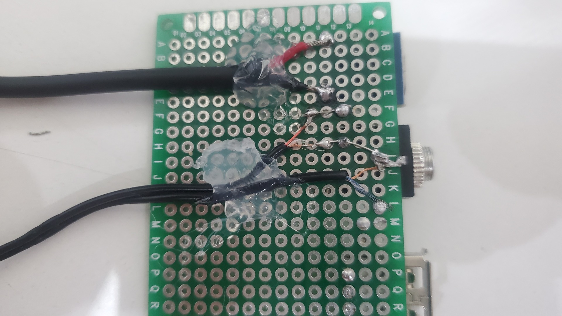
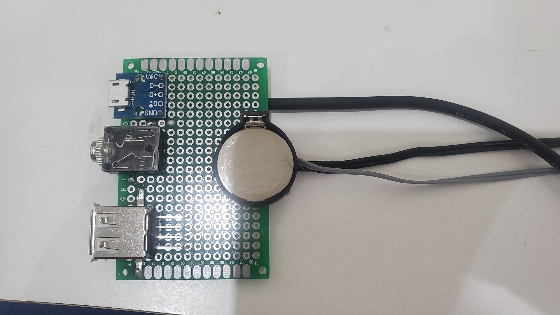
The goal here was to build a kind of “daughter board” with main connectors : power, audio jack, one usb port and the battery clock. All connectors are mounted and soldered on a 4x6cm breadboard.
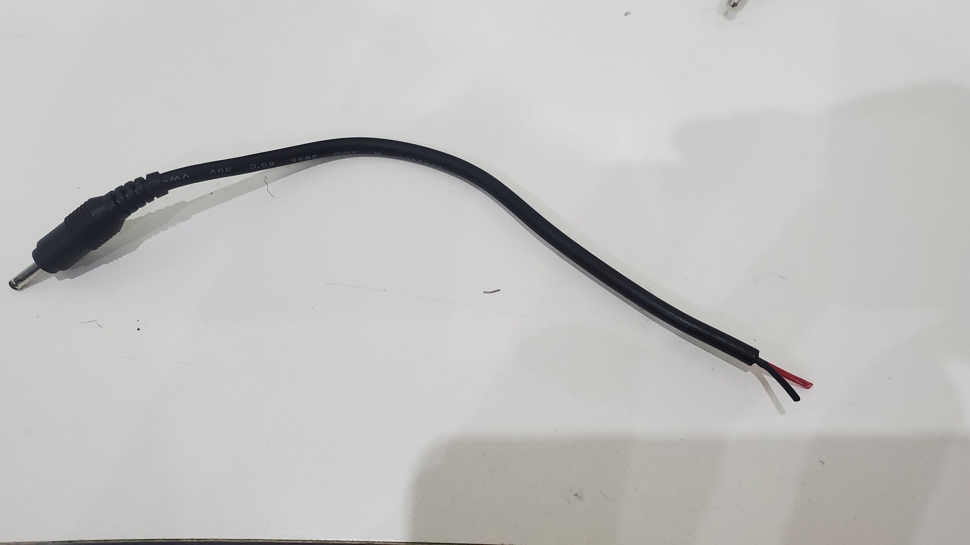
In order: place all connectors and solder them on the back. Then add audio jack, power cable and CR2032 battery holder; cables are also fixed with hot glue.
The USB connector is linked to a 4 pins rail which will be connected to one of the odroid C0 usb ports.
The audio jack will be connected to the jack output of the hifi shield because the jack connector on it is not on the same side as other audio out connectors.

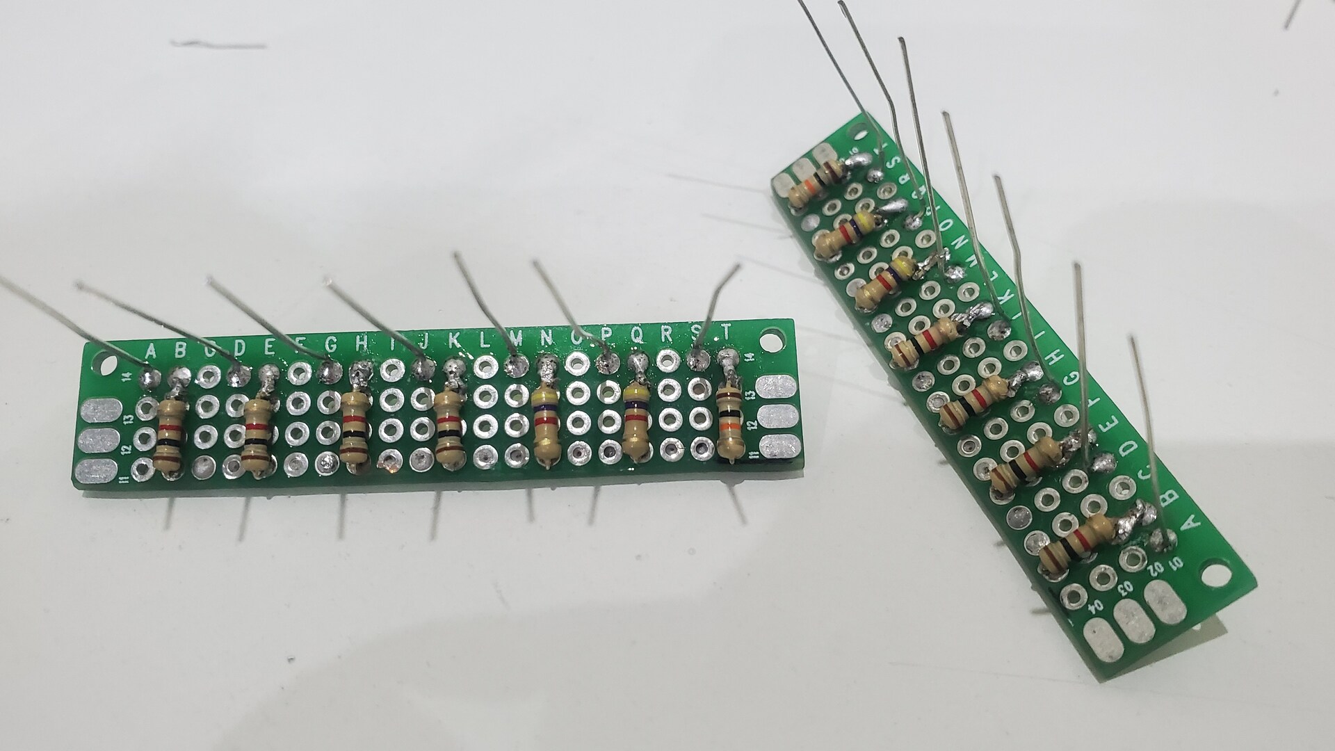
Vu-meter and battery monitor
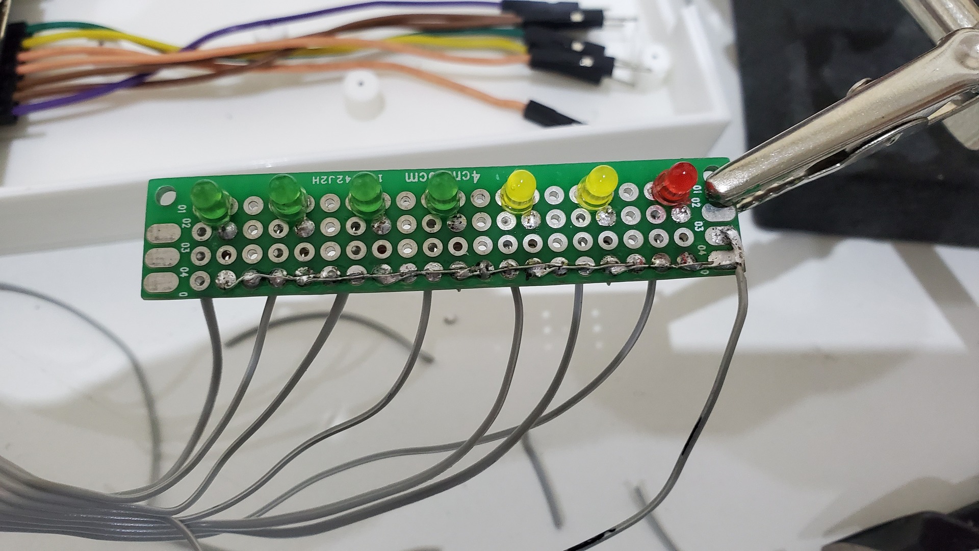
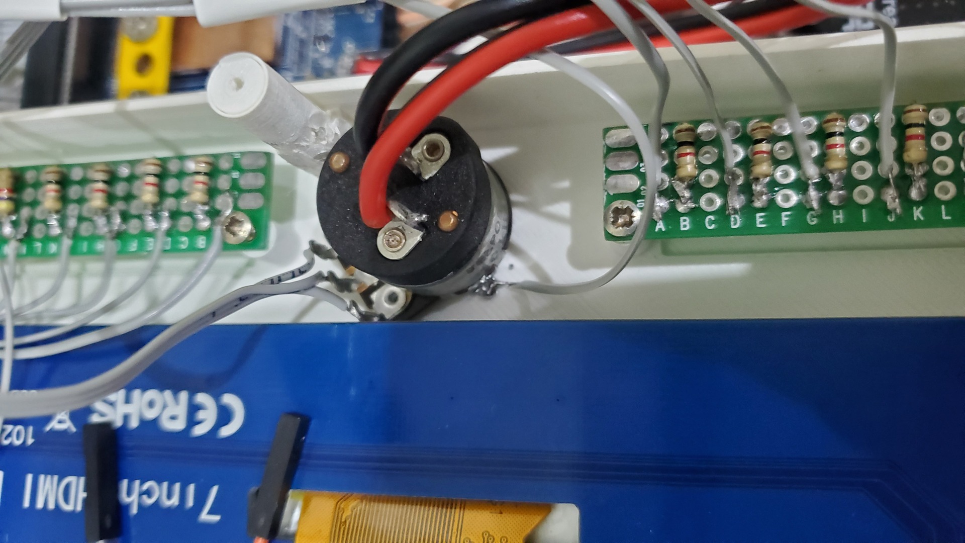
Like the connectors’ “daughter board”, the base for vu-meter leds is a 3x6cm breadboard, but this time, cut it in two parts. Each part contains 7 leds with their associated resistors. This provides 7 levels for left and right audio channels.
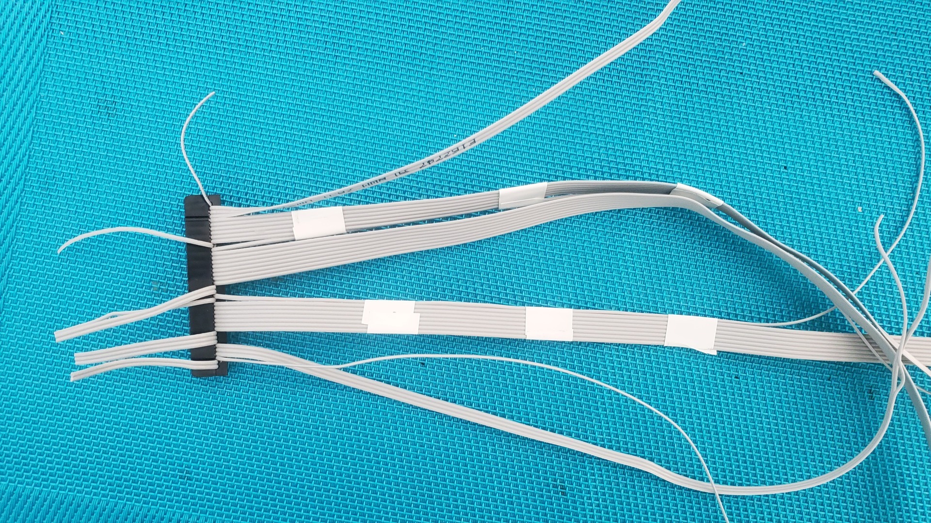
I used a standard 40 pins ribbon cable (IDE / PATA) to make it easier to connect all leds to GPIO ports.
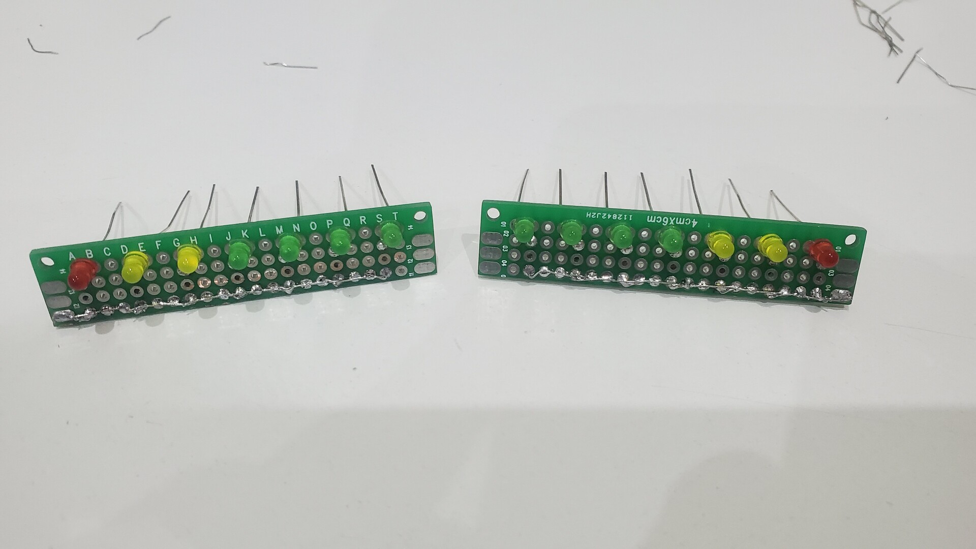

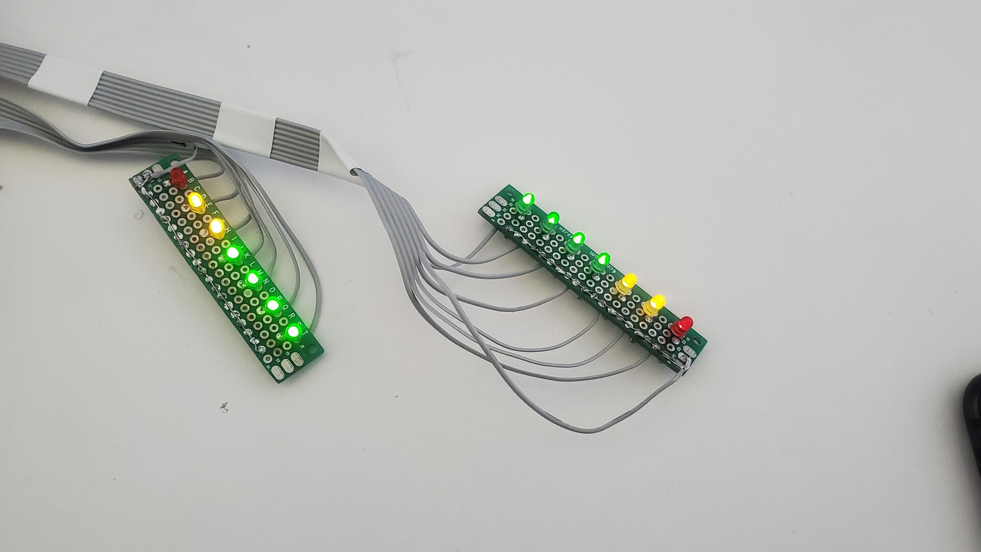
I wired the same way the 6 bits led board to display the battery level on the right side of the tablet:
Touch sensitive potentiometer
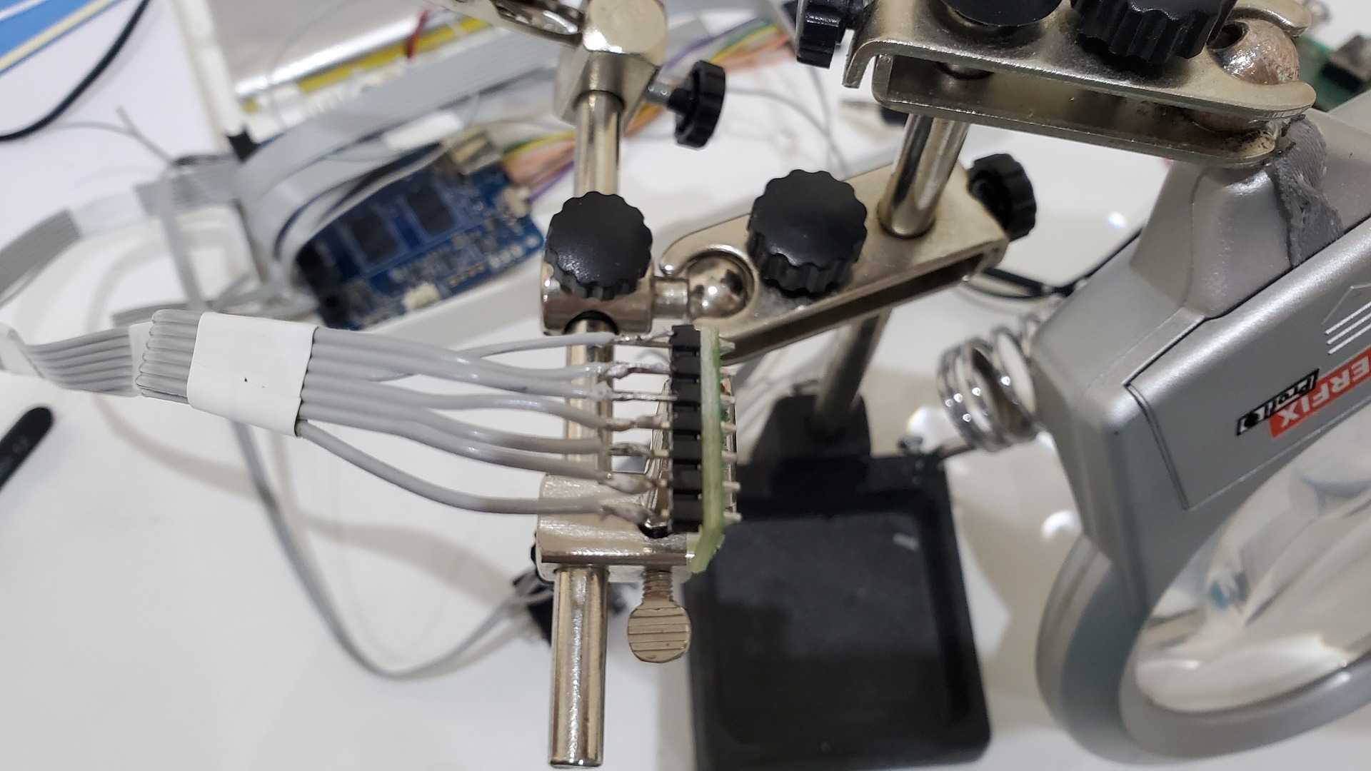
The potentiometer has also been wired to the GPIO through the ribon cable:
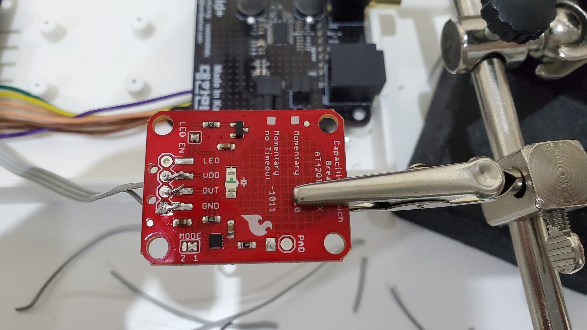
In order to make it touch sensitive, I used a breakout from Sparkfun. You may find any other brand, but it is important to get one with a “pad” pin. The idea is to use this pin and not the touch part which is hidden in the middle of the tablet. The pad pin is wired to the rotative part of the volume knob which is all metal and so, become touch sensitive.
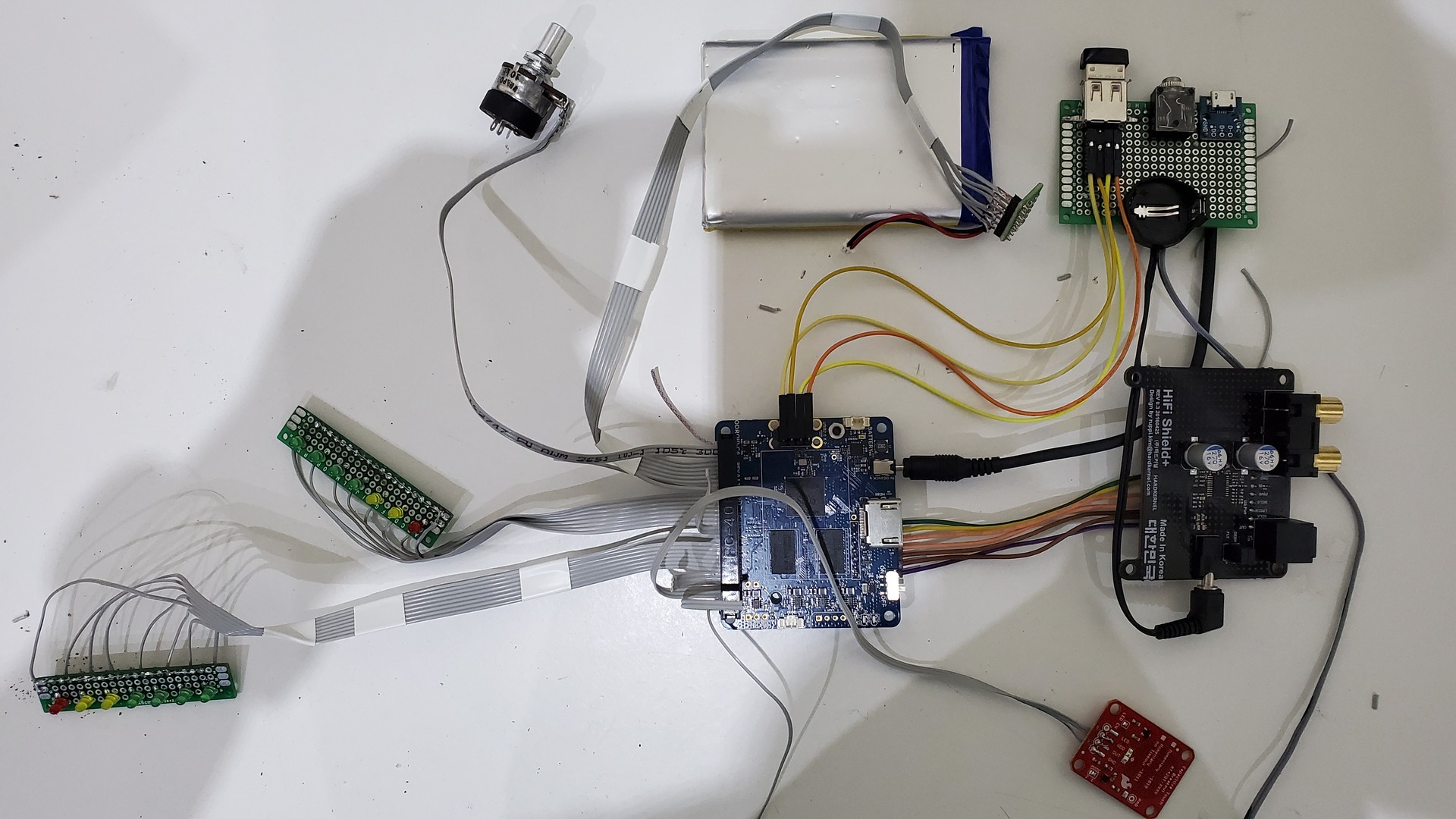
GPIO wiring and first tests
The following table show the wiring plan I used. Note that to optimise space inside the tablet, the 40 pins ribbon cable connector has been plugged in reverse order regarding GPIO pin. So the GPIO pin 1 correspond to the ribbon cable pin 40.
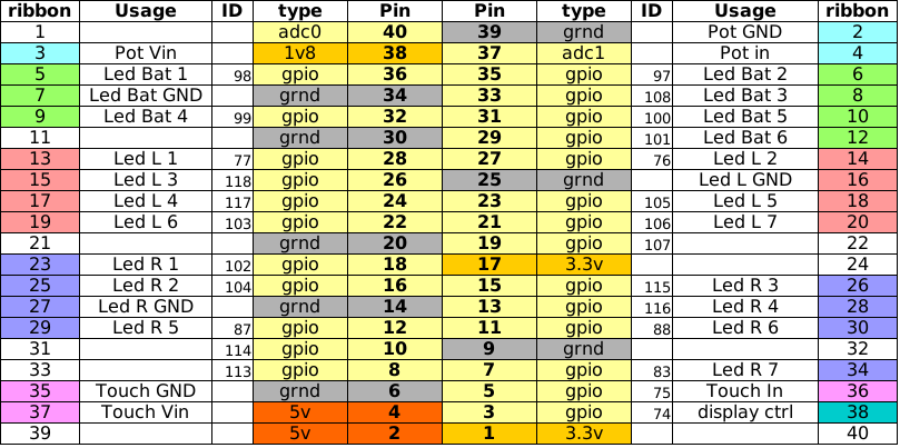
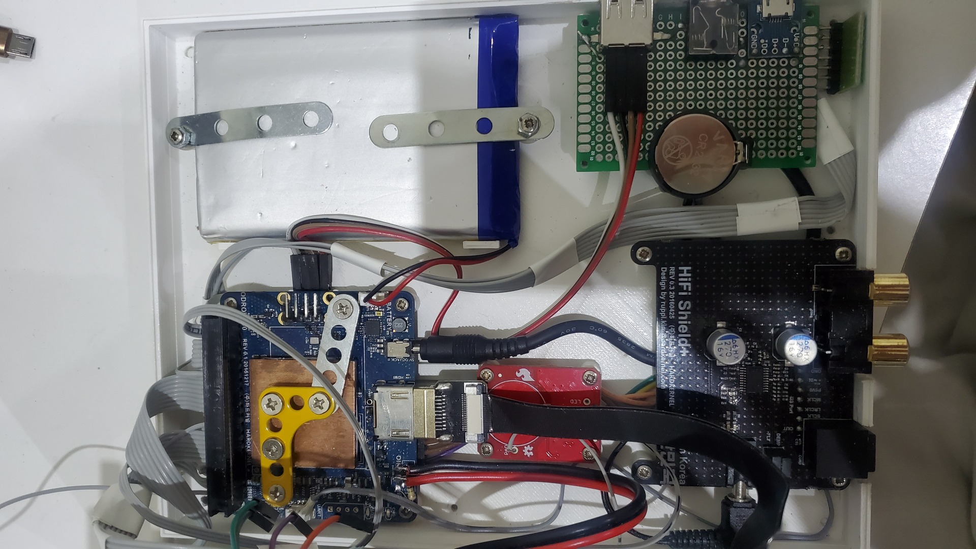
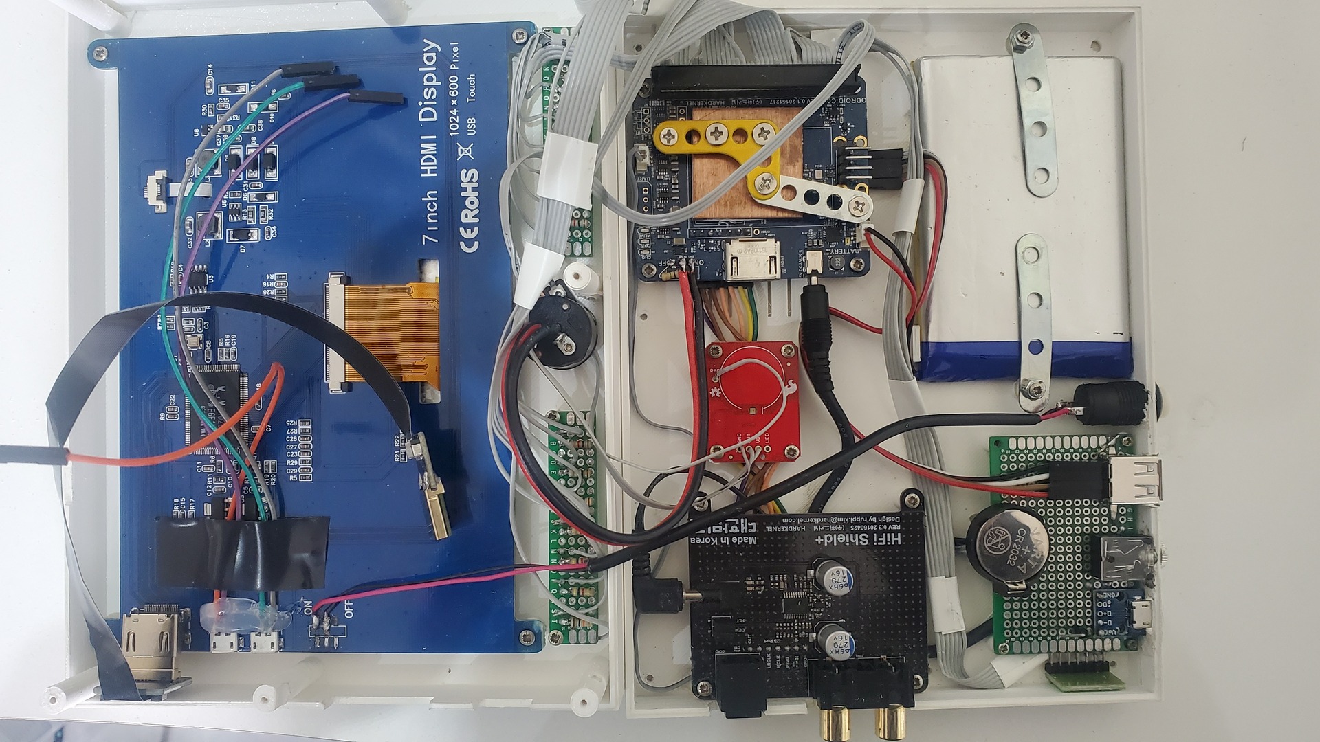
Below if a first test putting all together to check everything before the final assembly in the tablet case, except the display (I used a standard hdmi monitor for this first test)… hopefully no smoke, the Odroid C0 started correctly !
3D print and assembly
I modelized the case in Freecad. All files are availables on thingiverse : https://www.thingiverse.com/thing:4641846
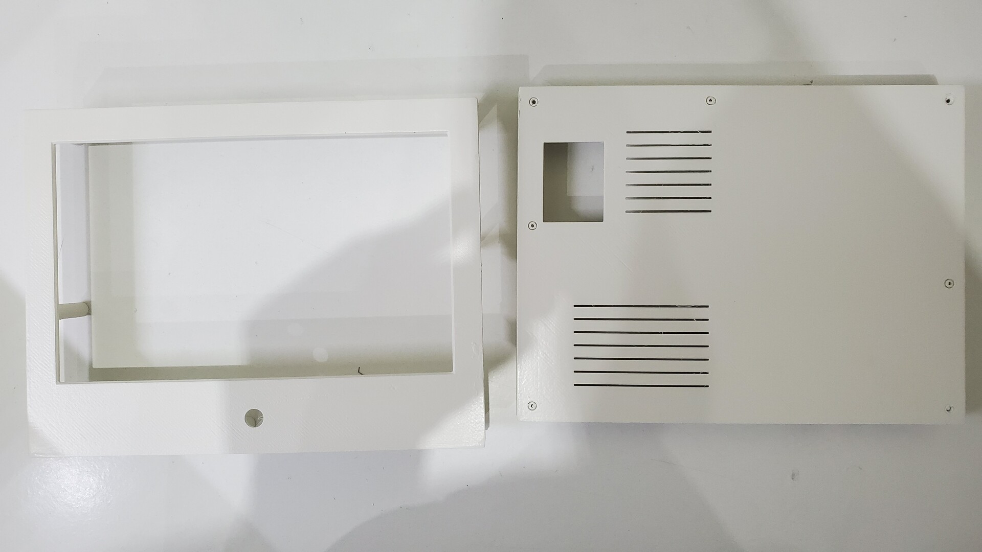
The skrew supports are filled and need to be drilled. It is more robust and give more liberty regarding the skrew types.
The 3D printed case, painted with white satin spray, for better rendering than “nude” filament:
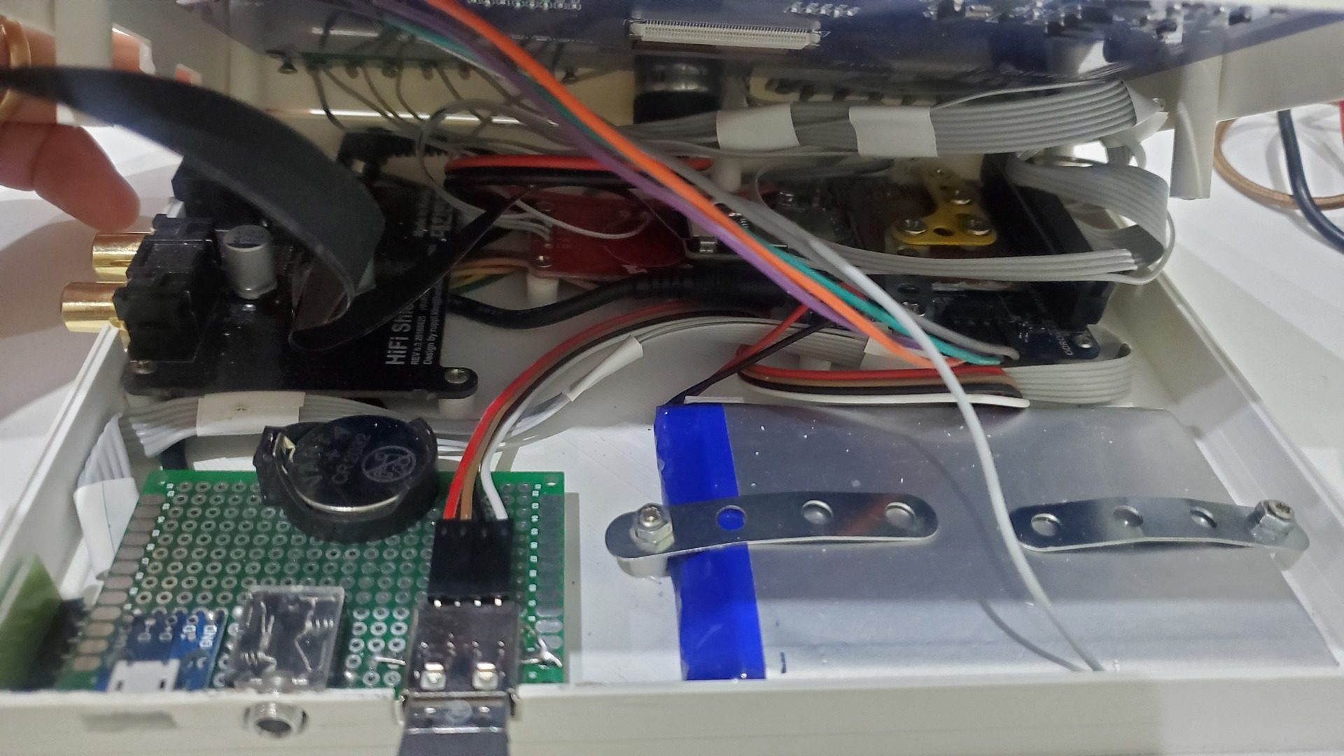
Assembly of the front part :
Assembly of the back :
Global view before closing the case :
Software part
The idea was to start from the base Volumio image for odroid C1 and a maximum of functionalities through shell scripts to avoid dependencies on the image (it uses an old Debian as base os). I used the version 2.834 (24.09.2020) : https://volumio.org/get-started/
All scripts I used can be found on my github : https://github.com/jit06/odrophile
Shell scripts have been stored in /opt and called form /etc/rc.local:
|
1 2 3 4 5 |
/opt/gpio_init.sh /opt/vu_meter.sh & /opt/adc_volume.sh & /opt/batterymon.sh & /opt/touchbutton.sh & |
Base install
Boot the image then :
- Install the “touch display” plugin (in category “Miscellanea”)
- Activate ssh by visiting http://volumio.lan/dev
- Replace boot.ini by boot.ini.vu7+ (rename)
- In boot.ini, comment out “disableuhs” if your microsd support it
Finaly, reboot : after a while, the screen now show Volumio interface on the touchscreen.
Setting up volumio
I used the following settings in volumio.
in “Sources”:
- Disable upnp, shairport-sync, dlna-browser
- Enable “show track number”
- Hide : albums, mediaservers, webradio , music library
in “Playback”:
- Output device : hifi shield
- Upsampling: 24/192
in “Appearance”:
- Change to classic interface (more suitable for small screen)
in “System settings”:
- Startup sound : off
- Allow UI statistics : off
Optimize the boot time
By default., boot time is terrible. Here is what I changed to speed it up a bit.
Disable unneeded services (your needs may vary) :
|
1 |
systemctl disable winbind nmbd samba-ad-dc smbd bfs-common lirc nfs-common plymouth-quit bluetooth cd shairport-sync |
The Volumio system put the c1_init call in /etc/rc.local instead of putting it in a hook in mkinitcpio. As this script take some time to execute because of the framebuffer initialisation, we can remove its dependency in systemd, so it starts early in boot process, in parallel of all other services.
In file /lib/systemd/system/rc-local.service comment the network dependencies :
|
1 |
#After=network.target |
Then, reload daemon :
|
1 |
systemctl daemon-reload |
Another thing to remove : pulseaudio as it is not used.
|
1 2 |
apt-get remove pulseaudio sudo rm /etc/xdg/autostart/pulseaudio* |
We also need to black list some kernel modules to free up GPIO pins and remove unused features. Here is the content of the /etc/modprobe.d/blacklist.conf file I used:
|
1 2 3 4 5 6 7 8 9 10 |
blacklist nfsd blacklist auth_rpcgss blacklist sx865x blacklist oid_registry blacklist nfs_acl blacklist nfs blacklist lockd blacklist sunrpc blacklist w1_gpio blacklist wire |
Finaly, I removed aml_i2c module as it generates a lot a errors and is not used. Unfortunately, putting the module in the black list does not work, so I inserted a line in /etc/rc.local, just before “exit 0”:
|
1 |
rmmod aml_i2c |
Leds vu-meter
The leds vu-meter is based on two parts. One is the “backend”, which analyses mpd output and generates sound level informations in ascii numbers from 0 to 7.
The second part is the “frontend”: it reads the output in realtime with a shell script that switches ON or OFF each led by driving the GPIO pins output.
The backend
The backend tool is Cava, a marvelous console-based audio visualizer. It had to be built from sources :
|
1 2 3 4 5 6 7 8 |
sudo apt-get update sudo apt-get install -y git-core autoconf make libtool libfftw3-dev libasound2-dev inotify-tools git clone --depth 1 https://github.com/karlstav/cava cd cava ./autogen.sh ./configure make -j4 sudo make install |
Cava does its job by reading a fifo. So we need to create a mpd fifo. To do so, I modified the template that Volumio uses, so the settings remain evan if parameters are changed in the Volumio interface.
In /volumio/app/plugins/music_service/mpd/mpd.conf.tmpl :
|
1 2 3 4 5 6 |
audio_output { type "fifo" name "mpd_oled_FIFO" path "/tmp/mpd_oled_fifo" format "44100:16:2" } |
Cava needs some tuning for our use case. In /home/volumio/.config/cava/config, I set the following. Note that I removed all non modified content in this blog post, but in reality, I kept the original content and I juste changed the parameters like below:
|
1 2 3 4 5 6 7 8 9 10 11 12 13 14 15 16 17 |
framerate = 30 # the more fps, the more cpu usage autosens = 1 bars = 2 # one for left, one for right method = fifo # read from the fifo source = /tmp/mpd_oled_fifo # the fifo in which mpd output goes sample_rate = 44100 # same as in mpd fifo configuration sample_bits = 16 # same as in mpd fifo configuration method = raw channels = stereo raw_target = /dev/stdout # output to stdout so we can pipe to our "front-end" script data_format = ascii bit_format = 16bit ascii_max_range = 7 # 7 leds per channel gravity = 200 # makes vu-meter more dynamic |
The frontend
The shell script used to read the Cava output is on github : https://github.com/jit06/odrophile/blob/main/leds_vumeter.sh
It uses the standard /sys/class/gpio interface to drive right and left vu-meters.
The vu-meter system is launched by a simple script in /etc/rc.local : https://github.com/jit06/odrophile/blob/main/vu_meter.sh
Volume Knob
Volume though ADC
Handling volume trough Volumio seems bugged. I tried to activate “software” volume in settings, but it crashes. So the solution was to control volume via mpd directly. The drawback is that the current volume is not reflected in the Volumio user interface.
To activate software volume in mpd (/volumio/app/plugins/music_service/mpd/mpd.conf.tmpl), add the following in “audio_output”:
|
1 |
mixer_type "software" |
Then, go to Volumio UI, “playback” options, then click “save” in order to regenerate mpd config file.
The script that handle volume is, again, on github https://github.com/jit06/odrophile/blob/main/adc_volume.sh
It reads ADC value from GPIO and changes volume using mpc cli.
Note that as ADC values go from 0 to 1024, I simply divided the value by 10 to get the raw volume value to pass to mpc (which accept values between 0 and 100).
Touch sensitive knob
As mentioned previously, the Sparkfun‘s touch pad is wired to the metal part of the potentiometer. The touch pad detect that the knob is touched and we can read the corresponding GPIO value (1 = touched, 0 = not touched).
I implemented a script that detect double touch and tripple touch in order to trigger respectively toggle play / pause and random play of 25 music tracks.
This script is here https://github.com/jit06/odrophile/blob/main/touchbutton.sh
It may seems a little heavy / complicated, but the problem is that inotify does not detect gpio change in /sys/class/gpio pseudo filesystem, even if the gpio edge is set to “both”. So I had to implement the double and tripple touch using some polling mechanism.
The play / pause toggle use the Volumio CLI, and the random play (tripple touch) uses a nodeJS script given by a community member : https://community.volumio.org/t/adding-random-tracks-to-queue-track-to-album-loader.
This nodeJS script needs a dependency to work. To install it, go to /opt and install the module :
|
1 |
sudo npm install socket.io-client |
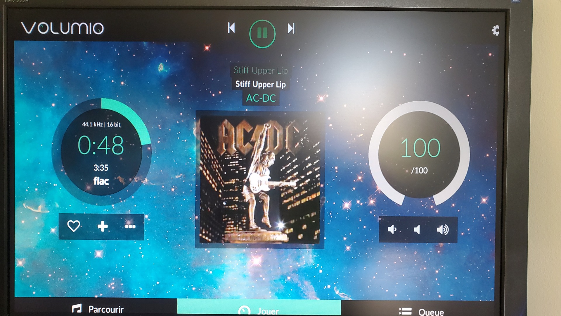
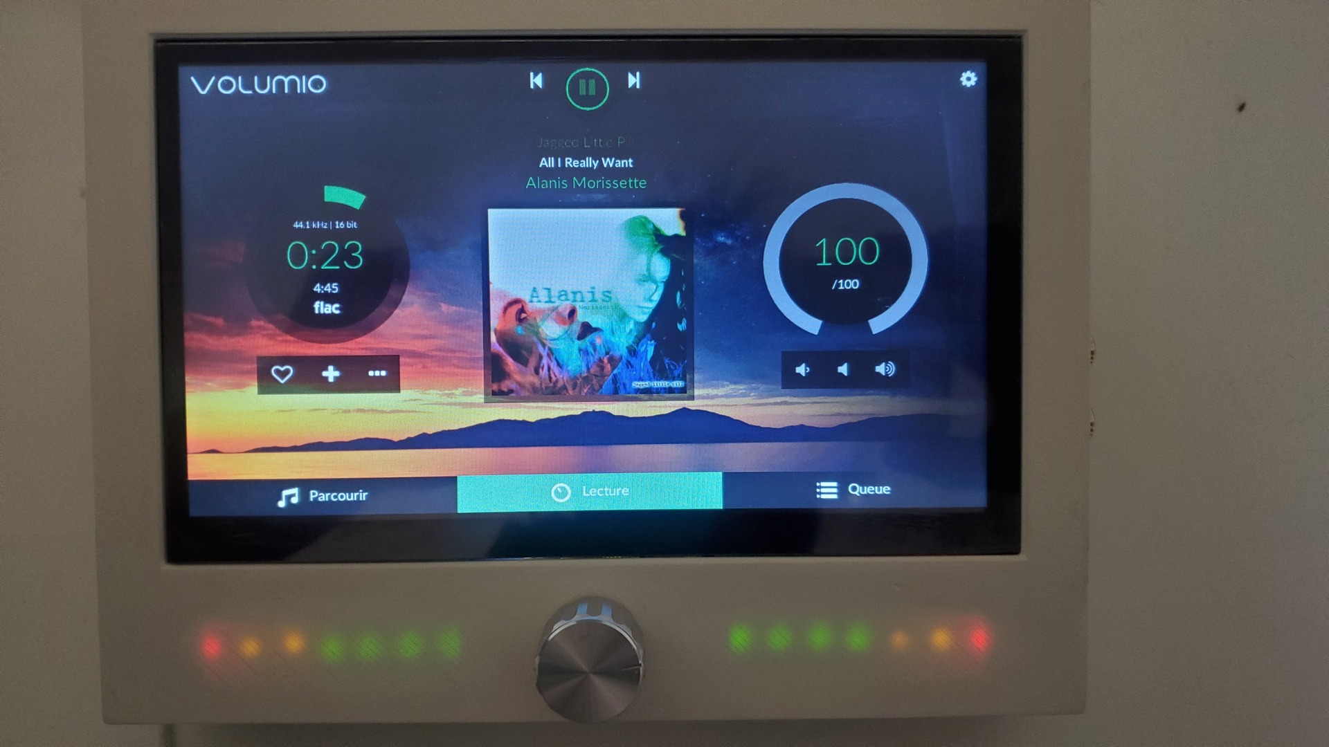
Final result
He are two photos and one video of the tablet playing some music:

Pingback: Odrophile update : am odroid based DIY audiophile tablet