Rflink with mqtt V2 : enhanced and minimized
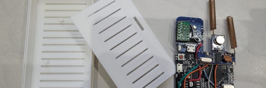
Some years ago, I built a custom shield for an arduino mega running Rflink. The purpose was to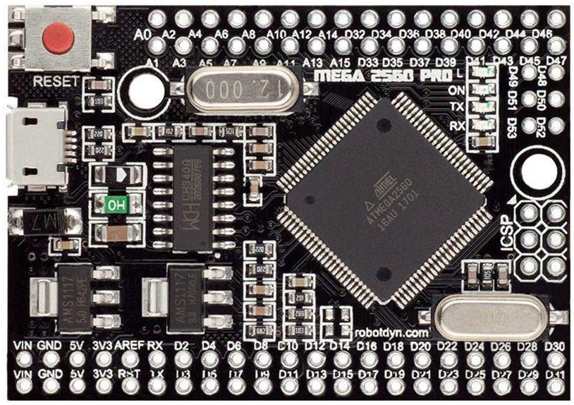 provide Rflink MQTT messages over ethernet. I recently built a new version which is more compact and with additional features.
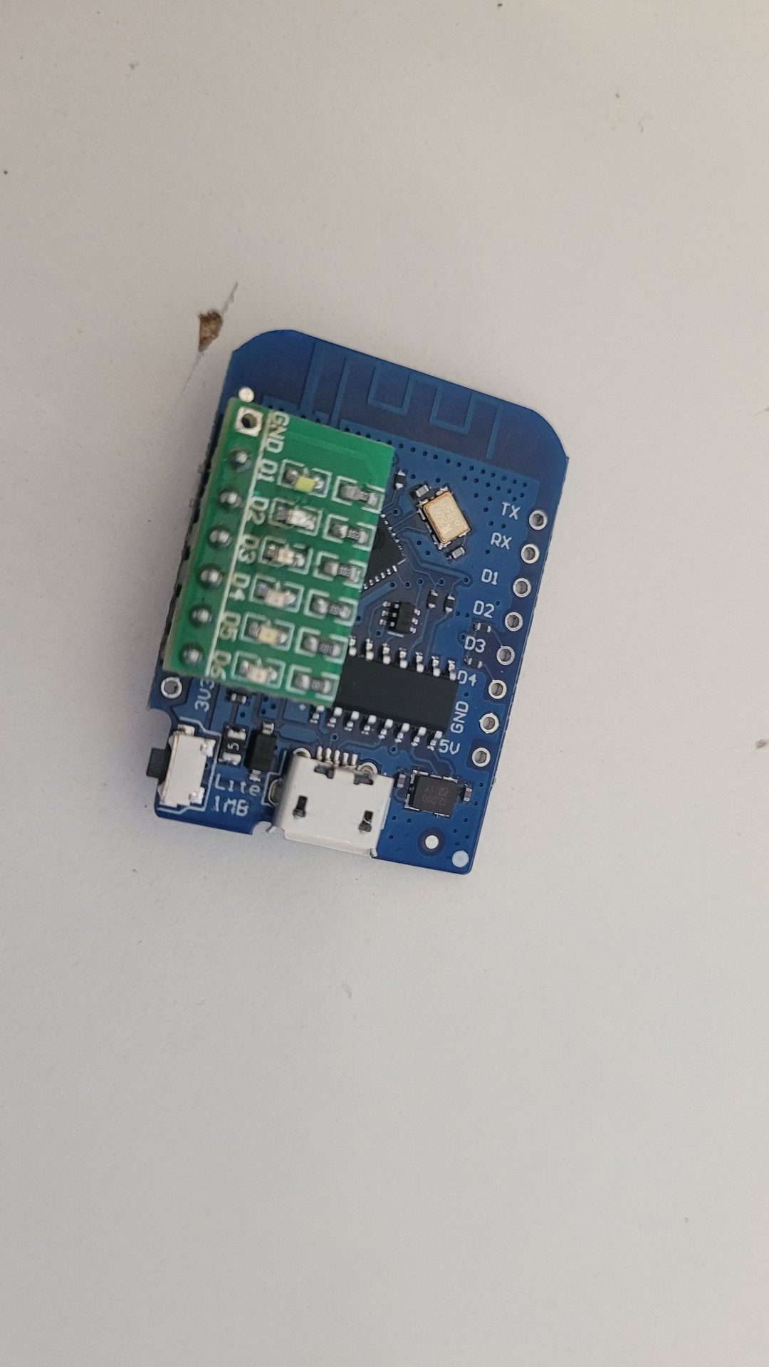
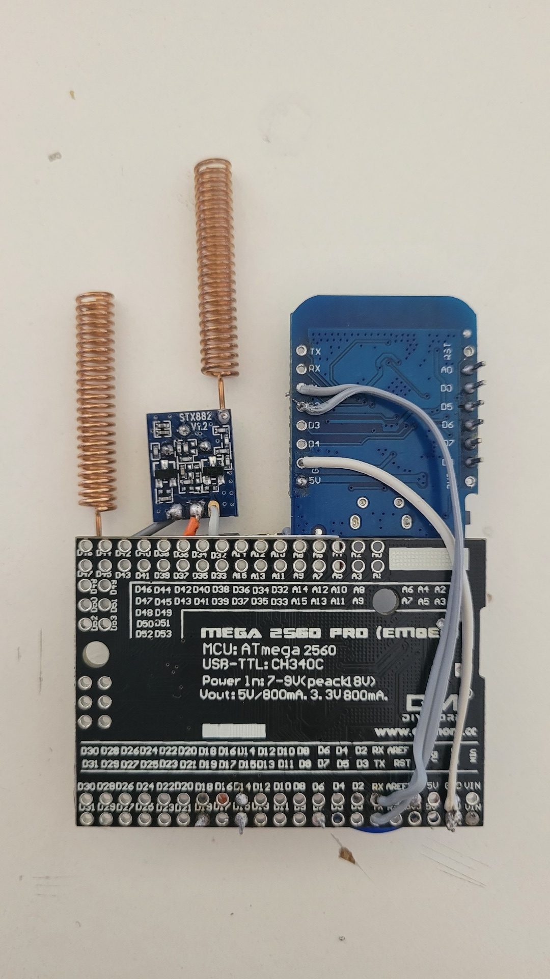
I replaced the arduino nano by a Wemos D1 mini (esp8266). I also used an arduino mega pro, which is smaller than the orignal one. The 433Mhz hardware has been changed to by SRX 882 and STX882 as they provide a better range than RXB6 and XD-FST FS1000A.
Main features are :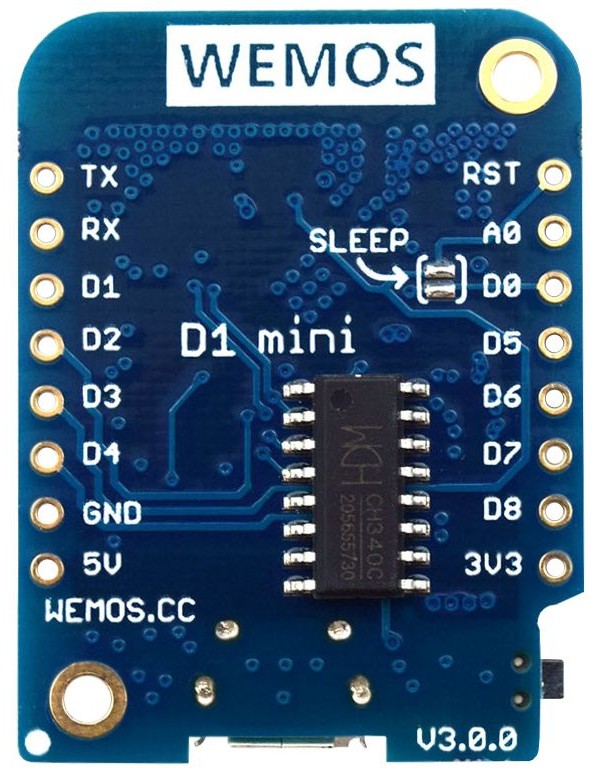
- Provides Rflink messages as json encoded payload over MQTT
- OTA updates of the Wemos D1 mini
- Leds indicators for Wifi, Mqtt, message in, message out
- Simple http interface to view Rflink and Mqtt messages
EDIT on 03.01.2023 : the First version was using SoftwareSerial on D1 and D2 to communicate with RFlink. But at 57600 bauds, from time to time some serial characters were lost and / or trashed. So I updated the code and the hardware to use SoftwareSerial for serial debugging and the hardware serial port is now used for the Rflink communication through D7 and D8 (using the swap() function). I updated the text of this post, but not the photos.
EDIT on 12.02.2024 : I released a new version with a better web interface and a reset feature. The pin D1 (gpio5) is no more used for led feedback. It can now be wired to the arduino’s RST pin via a 100 ohm resistor to automatically reset Rflink when no message has been received after a few minutes (usualy, this is because Rflink has crashed). Again, I updated the text of this post, but not the photos.
The updated source code is available on github : https://github.com/jit06/RflinkToJsonMqtt
The new 3d enclosure can be found on Thingiverse : https://www.thingiverse.com/thing:5415688
Hardware build
Used parts
- Arduino mega Pro : rflink works only on Mega hardware
- Wemos D1 mini : any esp8266 should do the trick
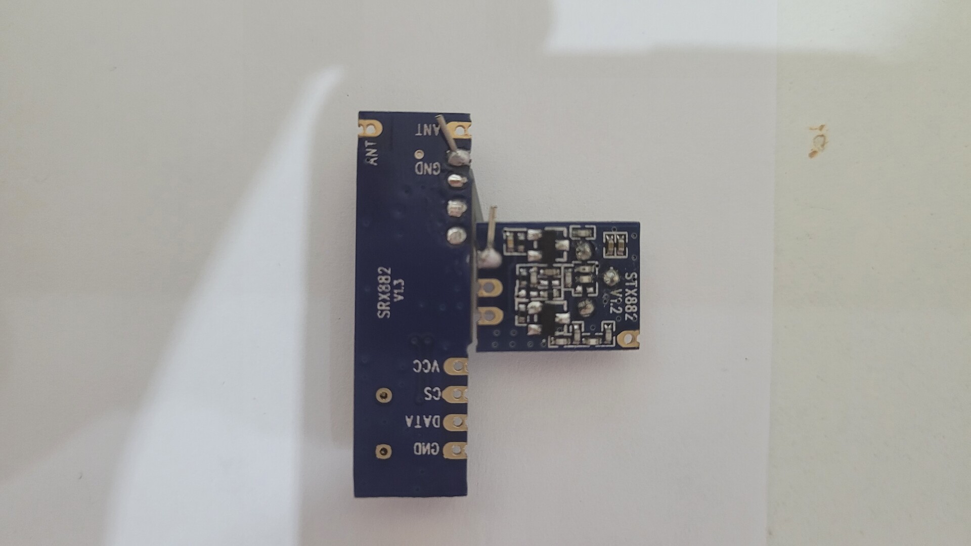
- SRX882 and STX882 kit with antennas : any other combinaison supported by Rflink will work
- Multicolor LEDs breadboard found on ebay
- Some wires / solder / soldering iron
Wiring tables
| SRX882 | Arduino Mega Pro | Comments |
|---|---|---|
| VCC | 3v3 | power for SRX882 |
| GND | GND | ground |
| Data | D19 | as seen on rflink instructions |
| STX882 | Arduino Mega Pro | Comments |
|---|---|---|
| VCC | D15 | |
| GND | GND | linked with SRX882 |
| Data | D14 | as seen on rflink instructions |
| Wemos D1 mini | Arduino Mega Pro | Comments |
|---|---|---|
| 5V | Voltage regulator pin | see below |
| GND | GND | ground |
| D7 | TX | serial connection (EDIT – was connected to D1 in the previous version) |
| D4 | RX | serial connection (EDIT – was connected to D2 in the previous version) |
| D1 | RST (via 100 ohm resistor) | Trigger reset signal (EDIT – was connected Led 2 in the previous version). The resistor is used to make a voltage divider which makes the voltage low enough on RST to trigger a reset of the Arduino |
| Wemos D1 mini | Leds breadboard | Comments |
|---|---|---|
| D0 | Led 1 – green | Wifi signal : blink while trying to connect, stay on if connected |
| D2 | Led 2 – blue | Mqtt connection : blink while trying to connect, stay on if connected |
| D5 | Led 3 – white | Blink when RF order is received and converted to mqtt message |
| D6 | Led 4 – orange | Blink when RF order is sent |
Build steps
No real complexity here : I mainly followed the rflink documentation and put in common some VCC and GND connections. Through, note that the ESP8266 is powered via one of the Arduino Pro voltage regulator. The Wemos D1 accepts to be powered through the 5v pin only if the voltage is between 4.3 and 4.6v.
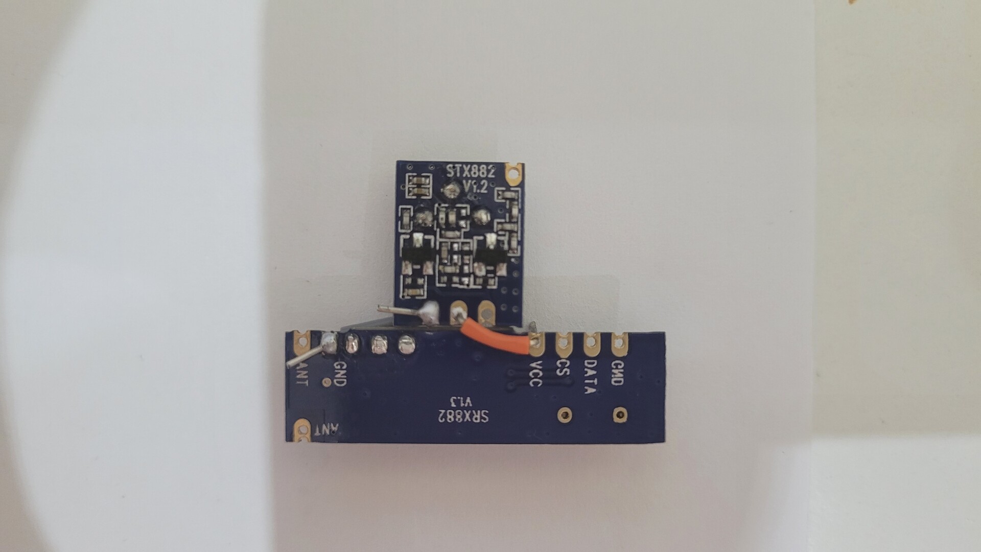
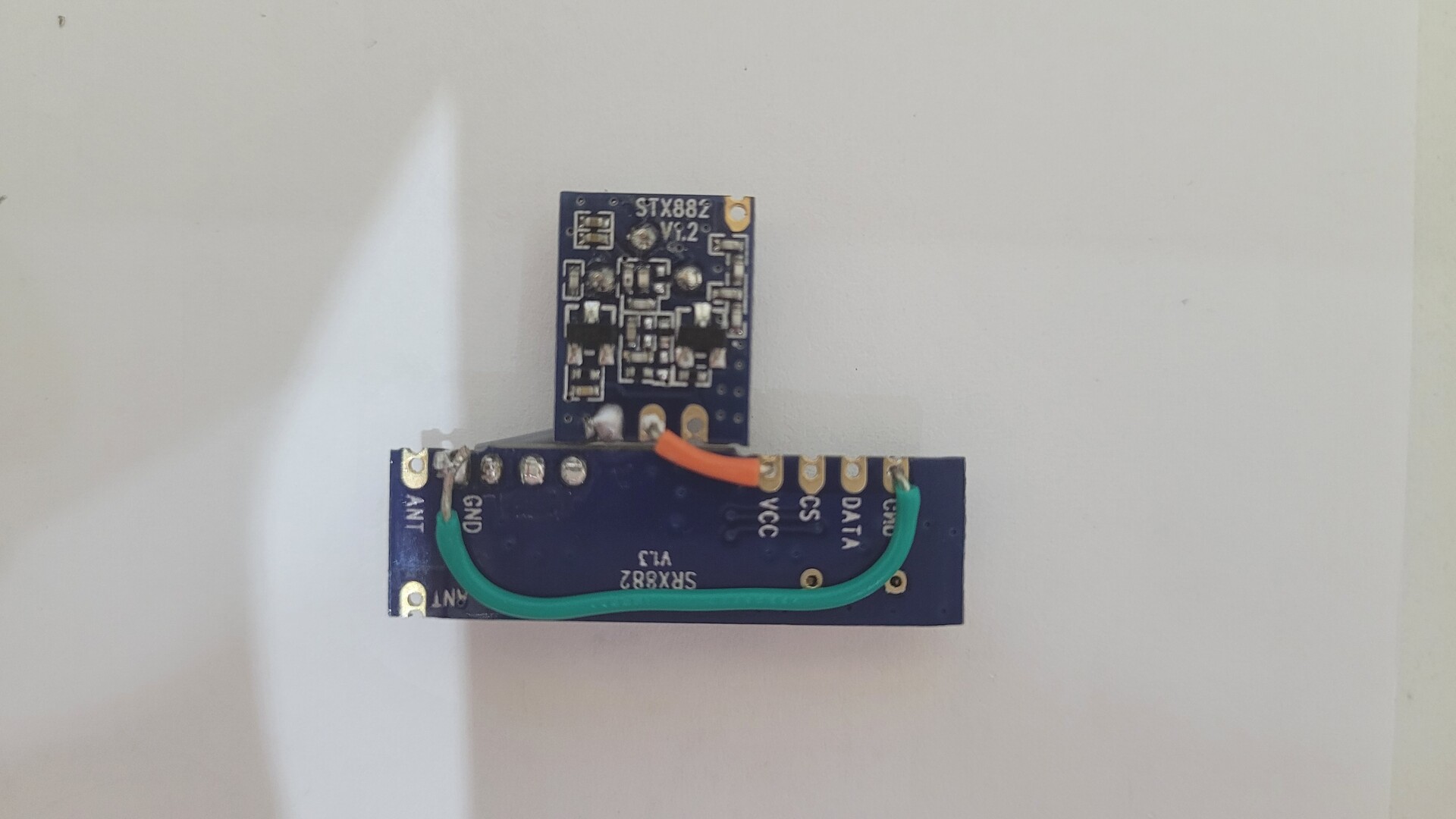
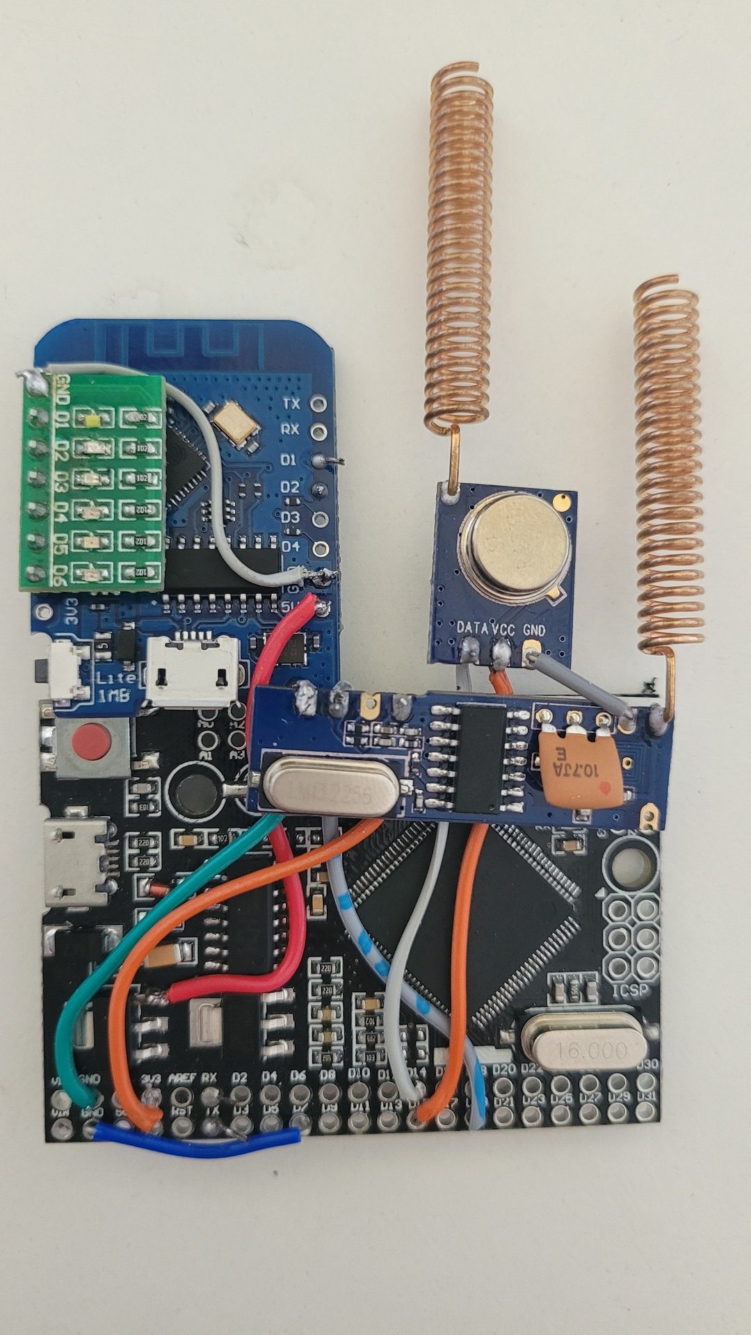
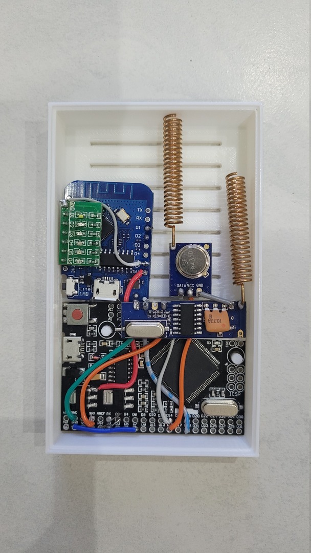
Wiring ground and vcc in common for SRX 882 + STX882 :
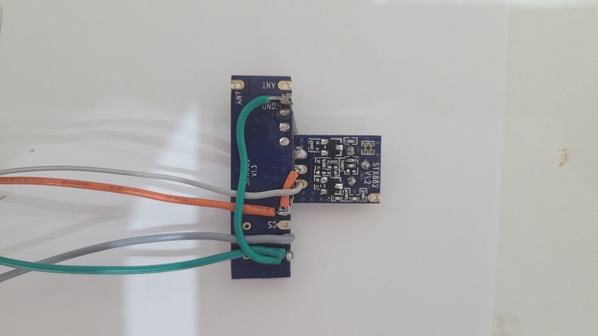
Wiring the two RF modules to the Arduino board
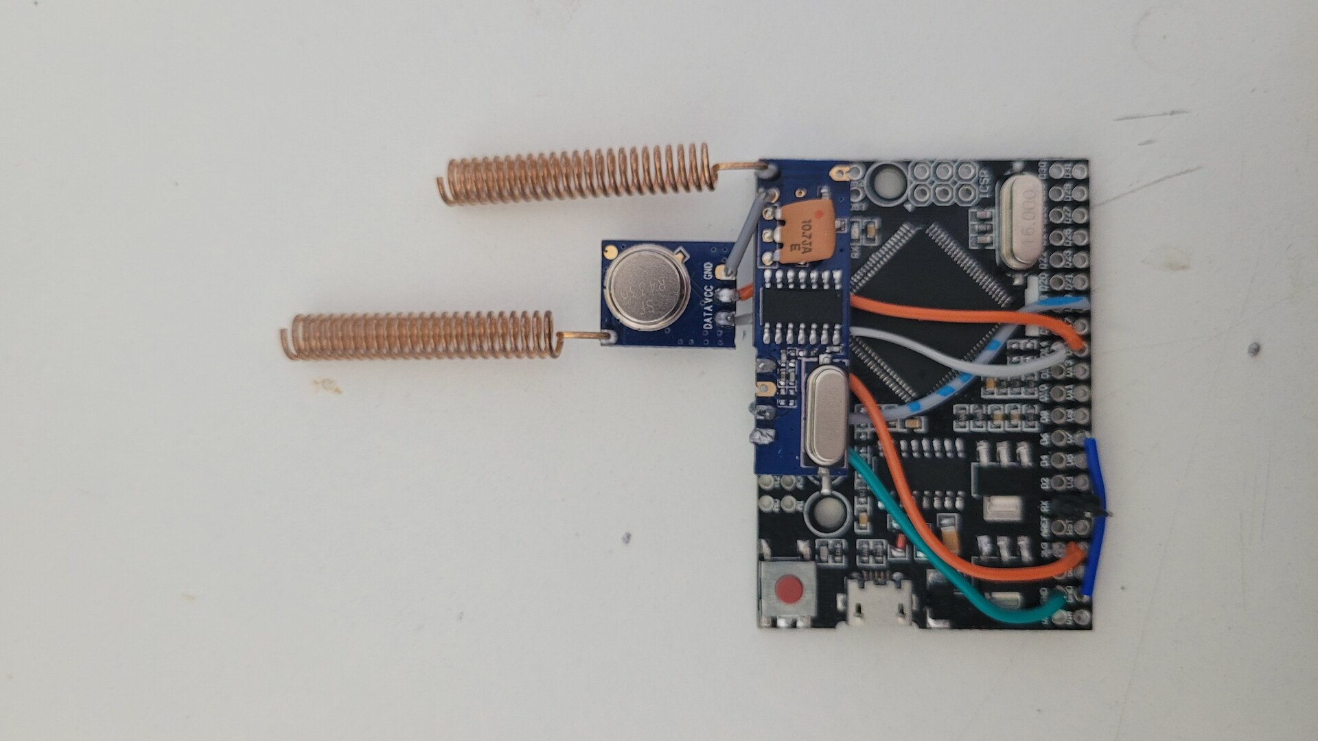
Adding leds module to Wemos D1 mini and wiring to Arduino as a Serial reader / writer. Basicaly, the Wemos use the hardware serial interface swapped on D7 and D8 (EDIT – in the previous version, it was using SoftwareSerial on D1 and D2) to communicate with the standard serial pins of the Arduino Mega
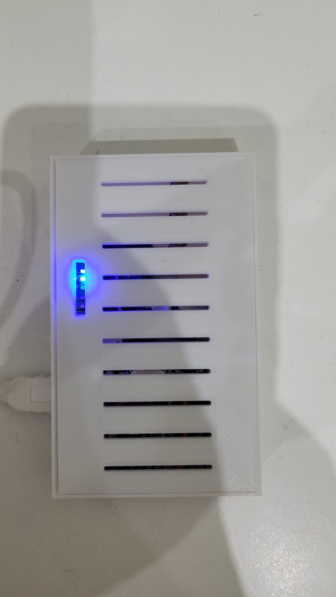
3D printed enclosure
The enclosure I made have been printed on a Anycubic I3 Mega in PLA. It tooks around 2 hours. The sources of the model (Freecad 0.19) are available on Thingiverse together the STL files.
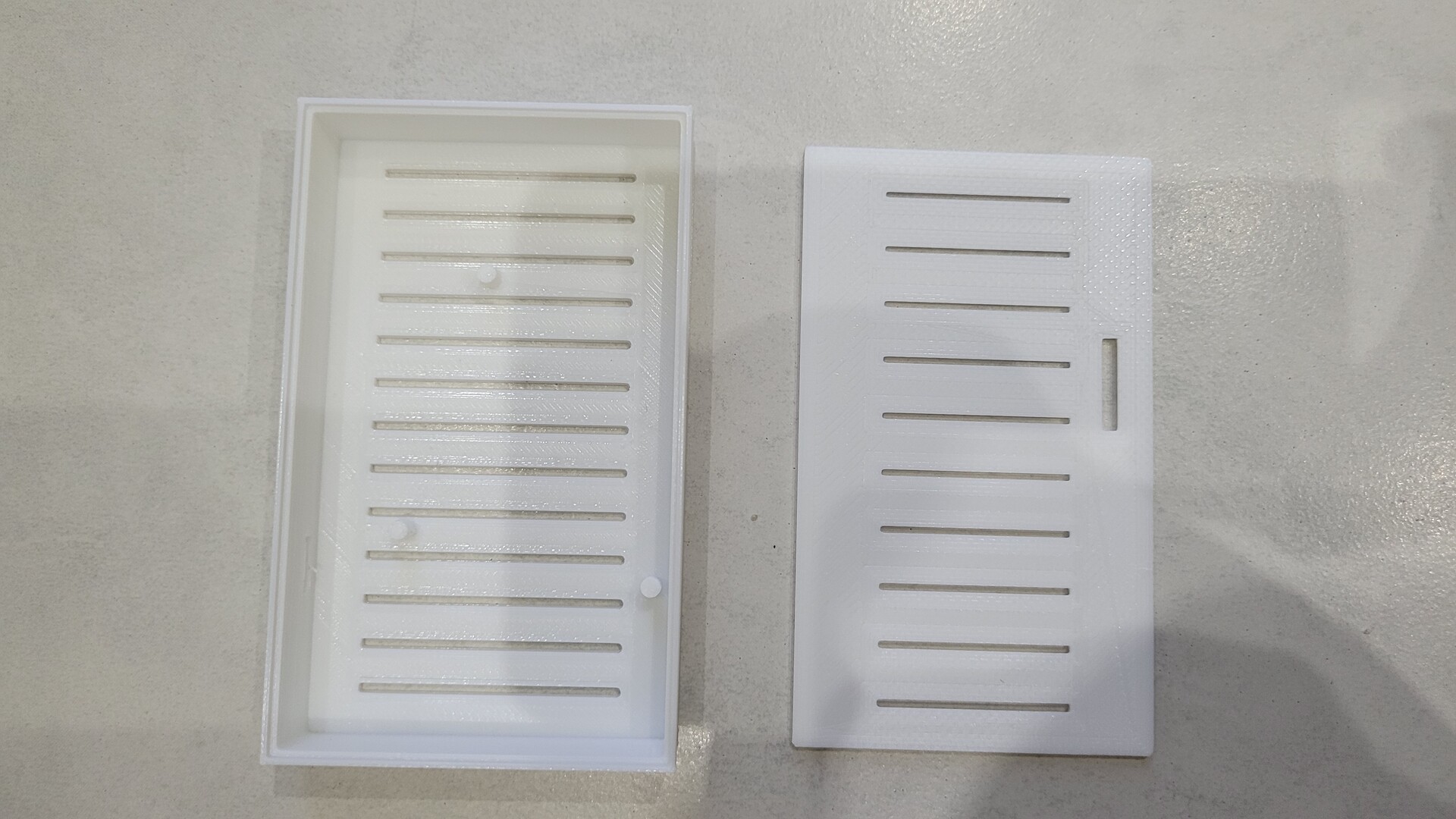
The enclosure is a bit tight so everything can be fixed without any skrew, by simply pushing it gently:
Software part
The original code as been modified in several ways :
- Adapted to run on ESP8266 with Wifi instead of Ethernet shield
- Added Leds handling
- HTTP server to show RF activity using websocket connections
- OTA update from Arduino IDE
- Refactored the main sketch to separate functionnalities in different files
The source code is available on my github and can be compiled with Arduino IDE (check Readme.md to install the dependencies).
Usage Example with OpenHab 3
Since the previous article in 2017, I upgraded from Openhab 2 to OpenHab 3 which has a new way to handle messages.
Here is 2 examples of how I use my rflink2mqtt gateway.
Using Oregon OS-THGR228-N-THGR122
- Create a channel with mqtt state topic : “rflink/Oregon_TempHygro/2DD1” (your ID will be different)
- Create an item for each properties, link them to the channel, use JSONPATH profile with the following expression :
- $.BAT for battery status
- $.HUM for humidity
- $.TEMP for temperature
Controlling a Chacon IO switch
- Create a channel configured like the following :
- MQTT state Topic : empty
- MQTT Command Topic : “rflink/Order”
- Custom On/Open Value : “10;NewKaku;0000800;1;ON;” (your id will be different)
- Custom Off/Closed Value: “10;NewKaku;0000800;1;OFF;” (your id will be different)
- Link a switch Item to your channel
As you can see, the gateway allows to write rflink orders directly to mqtt channel “rflink/Order” : the string is passed to Rflink.
Great project! I gathered all the required parts and printed the enclosure: THANKS for sharing!.
Looking at the pictures, the text and the instructions in the rflink documentation I think there is one thing in the wiring discription that is not correct. The VCC of the STX and SRX should not be connected since the STX should be powered using D15 as stated in the RFLink documentation. This also seems to be what you have done in the last picture, but in the text and other pictures it still looks like the VCC’s of the STX and SRX should be connected.
In addition I have a problem with compiling the RflinkToJsonMqtt sketch. My Common.h looks like (only defined the MQTT_SERVER_IP):
+++++++++
// MQTT Server IP
#define MQTT_SERVER_IP (192, 168, 178, 2)
// MQTT Server name
//#define MQTT_SERVER_NAME “mqtt.local.lan”
// MQTT Server mode : comment out to use MQTT_SERVER_IP instead of MQTT_SERVER_NAME
//#define MQTT_SERVER_MODE_DNS
+++++++++
But when compiling I get an error that there are multiple definitions of ‘SERVER’ …. See the output below:
++++++++++
Arduino: 1.8.19 (Windows Store 1.8.57.0) (Windows 10), Board: “LOLIN(WEMOS) D1 R2 & mini, 80 MHz, Flash, Legacy (new can return nullptr), All SSL ciphers (most compatible), 4MB (FS:2MB OTA:~1019KB), v2 Lower Memory, Disabled, None, Only Sketch, 921600”
Multiple libraries were found for “PubSubClient.h”
Used: C:\Users\arman\OneDrive\Documenten\Arduino\libraries\PubSubClient
Not used: C:\Users\arman\OneDrive\Documenten\Arduino\libraries\ESP8266_Microgear
c:/users/arman/onedrive/documenten/arduinodata/packages/esp8266/tools/xtensa-lx106-elf-gcc/2.5.0-4-b40a506/bin/../lib/gcc/xtensa-lx106-elf/4.8.2/../../../../xtensa-lx106-elf/bin/ld.exe: sketch\RflinkToJsonMqtt.ino.cpp.o:C:\Users\arman\OneDrive\Documenten\Arduino\RFLinkMQTT\RflinkToJsonMqtt/Mqtt.h:15: multiple definition of `SERVER’; sketch\Mqtt.cpp.o:C:\Users\arman\OneDrive\Documenten\Arduino\RFLinkMQTT\RflinkToJsonMqtt/Mqtt.h:15: first defined here
collect2.exe: error: ld returned 1 exit status
exit status 1
Error compiling for board LOLIN(WEMOS) D1 R2 & mini.
++++++++++++++++
Any ideas what could be wrong? Thanks for the help.
You’re right, there was a mistake in my wiring table : the STX is powered by the Arduino D15 pin. I corrected the article.
Regarding the compilation, I still need to try again on my side with fixed IP option.